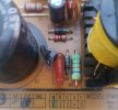
Hi, A capacitor on the PSU - PW808 get very hot recently, burnt out really, I was considering replacing it, but wasn't sure what the specification are, it was item C2 and it maybe affected C3 also... any parts list or something specifying the capacitors required? That would be fantastic of someone had these.
-
 The forum software that supports hummy.tv will be upgraded to XenForo 2.3 on Wednesday the 20th of November 2024 starting at 7pm
There will be some periods where the forum is unavailable, please bear with us. More details can be found in the upgrade thread.
You are using an out of date browser. It may not display this or other websites correctly.
You should upgrade or use an alternative browser.
You should upgrade or use an alternative browser.
Blown Capacitor - PSU Repair
- Thread starter potterpg
- Start date
Ezra Pound
Well-Known Member
I would expect C2 to have it's value & voltage rating written on it, also unlike bigger can type capacitors, C2 and C3 should be much more stable, I.e. I wouldn't expect them to 'burn-out', I would be looking for another component to have failed causing C2 to get hot, possibly the diode next to C2 on the PSU
Black Hole
May contain traces of nut
The markings on the components concerned tell you everything you need to know, or if you tell me what the marking say (or post a photo) I can fill in the details for you.
everthewatcher
Forum Supporter
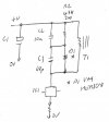
I've pulled the PSU out of a DTR-T1000 as it was easier than pulling the HDRs out. It's marked PW1003 and it's a reasonable assumption that the mains side of the cct should be the same for it and the two PSUs used on the HDR. C2 and C3 are part of the snubber network across the primary of the transformer and I can't see any way they should "get very hot... burnt out really". To make sure we're talking about the same ones, both are between C1 (120u/450V) and the transformer,Hi, A capacitor on the PSU - PW808 get very hot recently, burnt out really, I was considering replacing it, but wasn't sure what the specification are, it was item C2 and it maybe affected C3 also... any parts list or something specifying the capacitors required? That would be fantastic of someone had these.
Values are: C2 103K (10n) 630V polyester, C3 101K (
Update 18/7/23: That link to the datasheet is now dead so here's a link to it on Alldatasheet: Click
Last edited:
MikeSh
Well-Known Member
have it's value & voltage rating written on it,
The markings on the components concerned tell you everything you need to know
This:
suggests the markings may not be legible any more.get very hot recently, burnt out really,
Black Hole
May contain traces of nut
If a component is so fried that the markings can't be read, it is not reasonable to assume replacing it will solve the problem. Something caused it to fry, and unless that "something" is tracked down and sorted out it would be foolish to simply replace the fried component.
Blown electrolytics are a different matter - we know what the problem is (decomposed dielectric) and what they look like (domed end to the can). Those are components which have failed due to age rather than anything else.
Blown electrolytics are a different matter - we know what the problem is (decomposed dielectric) and what they look like (domed end to the can). Those are components which have failed due to age rather than anything else.
Ezra Pound
Well-Known Member
All of which was said in post #27If a component is so fried that the markings can't be read, it is not reasonable to assume replacing it will solve the problem. Something caused it to fry, and unless that "something" is tracked down and sorted out it would be foolish to simply replace the fried component.
Blown electrolytics are a different matter - we know what the problem is (decomposed dielectric) and what they look like (domed end to the can). Those are components which have failed due to age rather than anything else.
Black Hole
May contain traces of nut
I must get my glasses changedAll of which was said in post #27
I would expect C2 to have it's value & voltage rating written on it, also unlike bigger can type capacitors, C2 and C3 should be much more stable, I.e. I wouldn't expect them to 'burn-out', I would be looking for another component to have failed causing C2 to get hot, possibly the diode next to C2 on the PSU
Thanks for your replies everyone.Values are: C2 103K (10n) 630V polyester, C3 101K (1n0100p) 1kV ceramic.
From the photo, you will see that only C3 has burnt out, it was resting on the other one C2, hence why its discoloured, and probably wise to replace also.
The rest of the board shows no other issues, and the machine may of still been working, I just smelt the burnt smell, and turned it all off.

Black Hole
May contain traces of nut
Be very careful. It is possible C3 has failed of its own accord (dielectric breakdown resulting in a short-circuit), but I would be wondering whether something else has precipitated the failure.
Go ahead and replace C3 (note the 1kV specification), but when you power it up do so in a safe environment (in case of fire) and be standing well back (in case of exploding complonents). Use a mains extension lead from the wall, and an RCD breaker, and power up at the wall last. Buy more than one "in case" (it's a lot cheaper to buy several at once than one at a time).
I hope I don't need to tell you that the "naked" PSU board has mains voltages on it (even after power off, due to stored charge).
everthewatcher
Forum Supporter
Wow, that cap has clearly failed s/c.Thanks for your replies everyone.
From the photo, you will see that only C3 has burnt out, it was resting on the other one C2, hence why its discoloured, and probably wise to replace also.
The rest of the board shows no other issues, and the machine may of still been working, I just smelt the burnt smell, and turned it all off.
I've now pulled apart the early (V1) HDR which has the same PW808 PSU as yours. The layout is slightly different from the PW1003 but the snubber cct is the same although C3 is 68pF 1kV and is physically a lot smaller than the 100pF on the later PSU. C2 is 10nF 630V.

As you can see C3 takes the edge off switching transients from D1. C2 will be OK and R2 will have survived too. I'd replace C3 with a larger 1kV component as Humax did on the later ones. Can't see the value is particularly critical and a 100pF should be fine. I'd also check D1 is still a diode - if it's o/c it could explain the death of C3.
Here's the datasheet for the HER18: www.rectron.com/public/product_datasheets/her101-her108.pdf
Last edited:
Black Hole
May contain traces of nut
I'd also check D1 is still a diode - if it's o/c it could explain the death of C3.
But that would mean excess voltage has been applied to the SMPS controller chip (with the likelihood that also needs to be replaced)...your diagram also leads me to suggest a check that D1 is still a diode.
everthewatcher
Forum Supporter
I see what you mean but then how would it dissipate enough power to run warm? Partial breakdown might be one possibility but then that would take the voltage stress off C3.I was just thinking about the board under D1 looking a bit on the slightly 'burnt' side, and your diagram also leads me to suggest a check that D1 is still a diode.
Black Hole
May contain traces of nut
I give in.
 I haven't read any of the above as criticism, and I certainly didn't intend any. It's just relevant discussion.
everthewatcher
Forum Supporter
But I did advise checking it and nothing I have said since negates that advice. I was just musing on how it might have run hot.I give in. I became a bit suspicious of the diode before I saw your diagram.
I can see no earthly reason why anything or anyone should indicate NOT to bother to check it, can you.
everthewatcher
Forum Supporter
Of course there are two chunky bits of copper connecting C3 & D1 so what we might be seeing is the effect of heat being conducted along them.I see what you mean but then how would it dissipate enough power to run warm? Partial breakdown might be one possibility but then that would take the voltage stress off C3.
MikeSh
Well-Known Member
The resistor is a bit cooked too, but mainly at the top end, which I think supports that hypothesis.Of course there are two chunky bits of copper connecting C3 & D1 so what we might be seeing is the effect of heat being conducted along them.
