• The forum software that supports hummy.tv has been upgraded to XenForo 2.3!

    Please bear with us as we continue to tweak things, and feel free to post any questions, issues or suggestions in the upgrade thread.

PA Question

Black Hole

May contain traces of nut
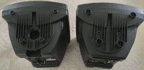
I have a pair of powered PA speakers (QTX as it happens), moulded plastic (as is common for such units). These have a socket for perching on a speaker stand with (IIRC) M6x1 clamp screws (I sourced some thumb screws for them).

They also have four cylindrical feet moulded in, and four sockets on the top so they will stack.

However, on the top surface they also have two M6 threaded holes, and I have no idea what those holes are for. Anybody enlighten me? I want to use them to fit a better carrying handle, but haven't got around to that yet (many years later...).
 
More likely for using a wall bracket, so you have one screw at the top, and one at the bottom, with a U-shaped bar screwed to the wall.

If ceiling mounting it only one screw would be used and the speaker would have been turned upside down, if only one mounting had been provided on the speaker.
 
If ceiling mounting it only one screw would be used and the speaker would have been turned upside down, if only one mounting had been provided on the speaker.
Might the second one be for a safety wire/chain, which I've seen used for hanging equipment in theatres.
 
safety wire/chain, which I've seen used for hanging equipment in theatres
I suspect by law, or if not then as a condition of their public liability insurance!

The top holes are symmetrically placed, so if only one were used there would be a torque on it. They are a little over 3" apart, about 78mm centre-to-centre. The only place the bottom of a bracket could engage is the pole mount (which does not sound unreasonable).

91C0AB37-364B-4311-9CAA-55EDA844B588.jpeg
 
More about these.

The published spec says "100W RMS / 200W max", so I hooked up a dummy load (3Ω) in place of the actual speakers and stuck a 440Hz sine wave into it. Just below the onset of clipping was ±20V, so that was delivering:

(20 x 0.707)² / 3 = 67W RMS

The actual speakers are (supposedly) 4Ω, so (presuming the voltage rail doesn't go up by much) that's only 50W RMS.

Now, I get that "max power / programme power / music power" is just double the RMS power and meaningless, but why is my RMS measurement only half the specification RMS?

If the test signal were a ±20V square wave (ugh!), the power delivered would be:

20² / 4 = 100W

Is it valid to specify the output power of an amp/speaker combination as the maximum unclipped DC power delivered to the load? If it is, then the rated power can only be achieved using a contrived waveform (ie a square wave, because any other waveform of equivalent RMS power would have peaks exceeding the clipping threshold).
 
I'm curious about the actual physical bits you used to get rid of 100W. Just lots of low wattage resistors in series/parallel? Or can you describe?
Just a big metal-cased resistor bought for the purpose:

1679140056012.png

...suspended in free air and not run for very long! It did get warm.

could the inductance be affecting it?
I don't see how. Which ever way you look at it, a 20V sine wave has an RMS voltage of about 14V, so square that and divide by the nominal resistance...

I am unsure whether the nominal 4Ω speaker impedance is the actual coil resistance or the effective impedance when you bung in a signal and the coil waggles in a magnetic field opposed by the coupling to the medium (air), but I'm sure the clue lies in the calculation 20²/4 = 100.
 
There were all sorts of tricks to 'increase' the claimed power rating of stereo amplifiers.

Run one channel at a time.
Do a tone burst so the power is being measured before the power supply droops.

1kHz is also the normal frequency at which such figures are measured.

as a side note, I recently (well just before I retired 3 years ago) had to build a dummy load for testing a three phase heater controller, The result was three loads, using the style of resistors you noted above, each load dissipating 5kW at 110V. Each load consisted of five 1/4" aluminium plates, each plate having six resistors as the load elements. The plates were then mounted with about 1" spacing, and a half dozen muffin fans mounted on the top sucking the air through between the plates. The temperature sensors on the plates were reaching just under 100 degrees C at equilibrium, just the thing to keep ones hands warm on a winters day when you have three lots of these running.
 
just the thing to keep ones hands warm on a winters day when you have three lots of these running.
Did you see that YouTube video (posted on here) about the transmitter tower with test dummy loads? They were in ventilated sheds outdoors!
 
Did you see that YouTube video (posted on here) about the transmitter tower with test dummy loads? They were in ventilated sheds outdoors!
I didn't see it, but I can imagine - probably starting in the 10-20kW range, possibly going as high as 500kW. makes global warming look sickly when that starts up ...
 
 
Back
Top