3D Printing / CAD

As to buying in, it's still a rapidly developing market. I'd think that year's sub would be the best way to go - that way you can get experience of the machines and materials and in a year maybe decide on a system to suit you.
I'm not sure I agree with it being a "rapidly developing market". Looking at what's available sub-£1000, I can't see there is much more development to do.

The year's sub gets me free induction, so it's worth it for the first year and I can still pay-as-I-go after that. The inconvenience of having to fit with their availability is outweighed by not having to provide space, maintenance, and tie up capital.

Something I have read: the arcs of curved surfaces will always be smaller than designed, because the print file divides the surface into straight-line segments.
 
Last edited:
This is where a professional designer will earn his keep. He(she)'ll know how and where to tweak individual dimensions.
If it is possible to do that, I'm sure there is a tool to do that in Solidworks or the like - and somebody coming up with a plugin for FreeCAD. It might be possible to compensate for shrinkage, but I am not convinced about the curl - that was not consistent across the prints, and seems to be more a question of taking care during fabrication.

Another approach is to add sacrificial elements. Overhangs require support structures to be included in the design which are removed later (usually designed as a low density mesh which just rubs away), but I see no reason this can't be extended to a small amount of machining post-print (such as sanding flat, or drilling to size a hole).

Or decide you've had enough and go play with something new :)
This is a skill for life, not a fad. My "thing" is not just an ornament made to find something to do with a 3D printer - the requirement came first, 3D lithography is an enabling technology.

What were the alternatives? I could have crafted a one-off by hand, but it would have been time consuming and I would not fancy making the four I required. I'm also not sure what base material I would have used. Machine tools (which I don't have) make a limited run more feasible. Either way I would have come up with a design more suited to the method of production. In that I needed a plastic part with a complex geometry, 3D lithography was a no-brainer.

So it's not a play thing, this is something I will use any time I need a part made for which it is suitable. Now I have crossed the initial barrier to entry (the learning curve) there will be more applications which previously did not warrant the effort.
 
Last edited:
If you are looking for a cheap 3D printer search the web for 'Peachy Printer'. It is a kickstarter project that is on the point of delivering production units before Christmas.
 
I'm not sure I agree with it being a "rapidly developing market". Looking at what's available sub-£1000, I can't see there is much more development to do.
From what I've read elsewhere the problem with the cheap machines is the speed and resolution is poor - curved surfaces are stepped and need work to get a good finish. I'd not expect prices to drop much more, but quality could improve significantly (much as inkjet printers have done).

Something I have read: the arcs of curved surfaces will always be smaller than designed, because the print file divides the surface into straight-line segments.
Yes, it's like an integration. The nearer you can get to an infinite number of segments the nearer to an accurate curve you'll get. This will presumably be limited by processor power/memory/file-size, and like resolution will likely improve with time.

This is a skill for life, not a fad. My "thing" is not just an ornament made to find something to do with a 3D printer - the requirement came first, 3D lithography is an enabling technology.
...
So it's not a play thing, this is something I will use any time I need a part made for which it is suitable. Now I have crossed the initial barrier to entry (the learning curve) there will be more applications which previously did not warrant the effort.
Fair enough. I didn't know how far reaching your plans were.
 
If you are looking for a cheap 3D printer search the web for 'Peachy Printer'. It is a kickstarter project that is on the point of delivering production units before Christmas.
That's very interesting, but I can't get excited about it. Like inkjet printers: cheap printers are expensive on consumables - have you seen the price of the resin?

(The concept is a UV laser writing in a pool of liquid resin to harden it - known as Stereolithography [SLA] - while the method that has been under discussion previously is known as Fused Deposition Modelling [FDM].)

For starters, the product will definitely be brittle; I very much doubt it would have been suitable for my application or any applications I can foresee. Limited to ornaments and space models. Short of advanced engineering resins (very expensive) this is a general limitation of SLA.

Then there is the printer itself. Heath Robinson had nothing on that. The Peachy Printer is the product of a home-brew experiment which should never have become more than a home-brew experiment (as an ex home brew experimenter myself, I know!). Okay, maybe that is a little harsh, but I hope everyone who has bought into this realises what they are going to get will be at best described as "temperamental". No way is it a consumer product.

What they have is a semiconductor laser, with the beam being deflected in x and y by a pair of mirrors driven by voice coils. Think of the way a laser light show projector works, writing simple graphics on walls or even smoke or the clouds. Accuracy doesn't matter in a laser light show - accuracy is critical in stereolithography, and this is an uncalibrated open-loop system where it is assumed that n mA in the voice coil creates an m degree deflection of the mirror (they are talking about closing the loop with positional feedback in a "pro" version).

The z axis is controlled by the level of the resin in the reservoir. The user provides two containers, one to supply and the other to receive resin (the latter is the working volume). The current xy surface is scanned in z simply by providing a constant slow flow of resin from the supply to the receiver, using a siphon and a dripper.

So, the user will have to calibrate the system (presumably using some kind of calibration routine) to specify: how quickly z is changing; the placement of the x and y centres of deflection over the liquid resin surface; the deflection of the x and y voice coils.

The unit will also be incredibly sensitive to vibration. Anybody who remembers school/uni physics experiments using light beam galvanometers or the determination of G with lead spheres and a mirror on a suspension wire (do schools do that stuff any more?) will know all about the sensitivity to vibration and draughts. The surface of the resin, being liquid, will also be subject to ripples - and ripples may be induced by the very process of transferring resin from the supply to the receiver.

In short, I think it's awful except as a tabletop demonstration of the principles of stereolithography. A great project to do with the kids, but as a serious contender for home 3D printing... as they say on Dragon's Den: "I'm out".

As a footnote: I am unclear how it is that the laser only writes on the surface of the resin. Why does it not penetrate to harden a considerable thickness? I appreciate there is an absorption in the resin, causing a chemical reaction to harden it, but wouldn't that be a bit fuzzy in effect? The SLA system I referred to in post 4 writes from below and draws the solid away upwards, and uses an oxygen concentration gradient to define the writable layer.
 
Last edited:
If they were to use a UV light source, a Texas Instruments mirror array (like is used in the Qumi projector), and an imaging lens (instead of a laser diode and two deflection mirrors), it would still be possible to achieve 100dpi over a 6" working surface.
 
Where were you when I was looking for a steer at the start of this topic?
Assuming you are referring to the immediately preceding post, then apart from my having slept a dozen times since then, you said:
Can anyone suggest a 3D CAD package that doesn't cost too much money?
I have a project that involves dipping a toe into 3D lithography (3D printing);
which doesn't sound to me like "This is a skill for life, not a fad." You've changed the description of your goal posts' location, if not actually moved them :)

If you are referring to another post ignore all the above :sleep:
 
"Skill for life" still doesn't stretch to a copy of Solidworks!

Let's say the goalposts have evolved. The target was the production of the "thing", but I have acquired unexpected skills with obvious future application in the mean time.
 
WTF is this about: the pictures show a Carbon3D unit, but £25 + £100 delivery??

http://www.ebay.co.uk/itm/advanced-...-photosensit/271734536392?hash=item3f44a3f8c8

image.jpg

There are practically identical listings at £25 with free delivery, and £1023 with free delivery. Something is very odd here, which leads me to suspect that even the £1023 price tag is some kind of trap.

http://www.ebay.co.uk/itm/Euroway-S...d4c4ef&pid=100009&rk=5&rkt=10&sd=271734536392

http://www.ebay.co.uk/itm/Photosens...d4c4ef&pid=100009&rk=1&rkt=10&sd=271734536392
 
Last edited:
The item price depends on the drop down selection, but they've set a fixed delivery charge.
I'd say it's a slight cock-up which is really unusual on Chinese ebay listings ... :geek:
 
Aha! I get it now. Select the actual printer from the drop-down and it's £1000+ (in all the eBay listings). The headline price is a cheap trick to attract clicks.

I reckon this is a knock-off of Carbon3d's unit, which does not appear to have come to market yet.

It also seems that what I was musing about (post 28) using a DLP chip to do the imaging is being developed, and may be the imaging used by Carbon3d:

http://3dprint.com/53286/gizmo-3d-printers-fastest/

The unit featured in the above article talks about bottom-up, but as far as I can see that means having a vat of resin with the build platform submerged in it - therefore a huge volume of resin. The Carbon3d method is top-down using a build "ceiling", and the oxygen membrane at the base of the tank crates a dead zone so that the polymerisation doesn't stick to the base.
 
Last edited:
Somebody tell me the answer to this one (if there is an answer): I installed FreeCAD by running the installer exe as admin. Now if I log in as admin, I can go into the Default Programs tool and assign the .fcstd file type to open in FreeCAD. But I can't do that in a user account, no matter what I try - even running the Default Programs tool as admin, or right-click on the file and try to change program - it just won't stick (and the file has become attached to Adobe Acrobat Reader as a result).
I have found my own solution to this. It required multiple passes of registry cleaning with CCleaner to kill off erroneous entries relating to FreeCAD, after which the "Open With" right-click dialogue worked properly to let me choose FreeCAD and set it as the default handler for that file type.
 
6 years on and I've resurrected this. Needless to say I forgot everything to do with using FreeCAD (or even that I used FreeCAD last time) and practically had to start again. In the intervening period, I haven't had a need for 3D print sufficiently great to warrant the time involved.

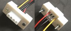
I want to fit an externally-accessible HDD power point to my home-brew PC ("ZEN"), to support the eSATA port (not eSATAp – I slipped up there). The only existing commercial solutions (a panel-mount Molex) are expensive and unavailable. My concept is to 3D-print an adapter bracket which makes a normal cable socket panel-mounting.

As just a one-off, I could simply bodge something (probably in less time than I've been buggering around with FreeCAD). However, I have been contemplating the trade-offs between buying a printer and outsourcing (again!). The price has come down, and it's just the sort of thing I could have been playing with during lockdown (it looks possible to build my own, and I really like the Delta type). On the other hand I have a busy enough life (normally) and a 3D printer would likely just sit gathering dust.

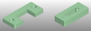
The first problem was coming up with a design concept which would be manufacturable. Pressed metal sheet would be ideal, but I have no way to do that. Will a plastic printed part be strong enough to withstand the insertion force and the waggle to unplug? Don't know. A plastic bracket will need to be in two parts, because it needs to locate the Molex using just the lugs so the Molex has to be trapped in, and ideally without having to dismantle the Molex (remove the crimped contacts).

Having mulled that over in the back of my mind for several weeks, I bit the bullet a couple of days ago and went for it. I went back to my 2015 design files to find out what I used then (remembering this thread would have helped). I was driven up the wall by the floor plan drawing being "broken" when I tried to extrude it into the third dimension, despite having chased down the constraints – which turned out to be duplicated lines (how did they get there?).

If you look at a Molex you'll see the lugs are bevelled. I could make right-angled notches ("pockets"), but how to make them bevelled? It turns out the answer isn't "chamfer", but "draft" – in this case meaning (apparently) something like the draft of a boat, and enables any particular face on the 3D model to be assigned an angle off orthogonal.

It didn't help that I am using FreeCAD 0.15 on Win7 whereas the current version is 0.19, so much of the on-line documentation assumes at least 0.18. No, I didn't want to risk breaking everything by updating software! I would have installed the Linux version on ZEN had 0.19 been available in the Mint repo. (Incidentally, it seems like 0.19 is less critical on constraints – so long as areas are "closed", the locations of features are defined by where they are on the drawing, so really there's no imperative on total constraint... although constraints are useful in an engineering situation.)

Anyway, late last night I finally had STL files (manufacturable 3D part models) and was ready to outsource... only to find the maker community hub 3Dhubs has gone commercial only. Fishing around I came up with Treatstock, which seems to do something similar, and placed an order with a business in Eastleigh for a total of $7.14 inc delivery (Treatstock seems to work in USD only).

My parts are small, so it is hard to compare this price with the cost of my 2015 print, but certainly it suggests there is no economic argument for having my own printer (although it might be justified on other arguments, such as hobby value).
1623574236938.jpeg
 
And thar she blows!

DC0C3242-9DA7-45AA-A7F2-D81522F8B47B.jpeg

The print shrank about 1% so I had to file it out a little, but the nuts press-fitted OK (and I undersized the screw holes anyway, so they could be drilled to the correct diameter). It feels plenty robust enough.

Actual cost: not in yet.
 
I've installed it
What is it mounted on? Could you show another picture in situ?
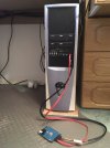
I just have a dangling cable coming out through the back (where the horizontal expansion slots were) on my work dev. PC, along with a dangling SATA cable. But that's a complete cheap lash-up built out of old and new bits.
I would have installed the Linux version on ZEN had 0.19 been available in the Mint repo.
0.18 is (on LM 20.1 anyway). 0.19 is easily added using the PPA.
 
0.19 is easily added using the PPA
I've not experimented with that yet.

Could you show another picture in situ?
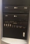
Not easily, or at least not that would convey much information. The "nose-cone" of the full tower case is a plastic molding and there's a convenient flat bit under the bottom 5.25" bay (where the port module with the eSATA is). The plastic is 2mm thick, and I simply mounted the molex from behind that with a pair of c/sunk screws into the captive nuts of the bracket. I have then tidied the whole thing up with a stick-on black fascia (double-sided tape) to match the colour of the drives instead of a patchwork of colours.

I had to make the hole in the fascia large enough to take the mating connector, because I only accounted for the panel being 2mm thinck not 3mm. If you want one the housing part can be slimmed down as required.

Incidentally: I've discovered that the "Molex" connector is actually an AMP connector (the original Molex is slightly different), and Molex then started to make a copy of the AMP connector.
 
Back
Top