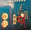
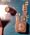
I have a HDR1000S and HDR1010S, both not recognizing the HDD. With plenty time on my hands I decided to try to fix them. Both discs checked out ok connected to a PC and using Discinternals Linux reader. Looking at the SATA spec, there are two data channels each of two conductors which should be capacitively coupled. Under magnification the tracks are visible, going diagonally from the disc socket towards the processor, with four chip capacitors visible. I confirmed there is continuity from the socket to the capacitors, the capacitors read as 9nF, and there is a credible resistance on the processor side showing that there is continuity there. So the problem is not the disc connecting to the processor. I also tried an alternative data cable and external power to the disc. Next I checked each voltage convertor on the main board. These are recognizable by having a square inductor with some capacitors and semiconductors and there are about 10 of them. I checked the DC and ripple voltage on each, high ripple being suggestive of capacitor deterioration. The only suspicious reading was from the one between the processor and the SCART socket which is probably the processor supply. Modern processors use low voltages, but 0.93V seems a very low and odd voltage. Both units were the same. I got a data sheet for this voltage convertor controller chip (A0Z1025D). It works by having its output voltage reduced to 0.8V by a potential divider and fed back to control pin. This voltage was correct on the board, but probing it tended to make the processor reset. I tried injecting up to 2.5V into the convertor output, and forcing the feedback pin to different voltages, which again tended to make the processor reset. At some point it started seeing the recordings again, and worked for a few days. This suggests my interference temporarily re-made an intermittant open circuit. I would add plated thru-hole to resistor and capacitor as possible failure candidates. This is how the different layers of the multi layer board are connected together. I looked at the potential divider which sets the 0.8V feedback, which is on the back of the board. It is not possible to check the resistor values in circuit other that to see a lower limit to what their value might be. The 5K reading is consistent with the recommended values in the data sheet. Apart from the expected two resistors of the potential divider, there is a third resistor connected to a track which heads towards the processor before disappearing to a different level. It measures as 27K and is connected to about 1.2V which means it is reducing the convertor output. It is possible that it is part of the power saving features and adjusts the voltage depending on what the processor is doing. I can't find a data sheet for the processor, which has been identified as a Broadcom 7346/56/55 in other posts. Does anyone know what the correct processor supply voltage at this point is on a good machine or on the processor data sheet?