Black Hole
May contain traces of nut
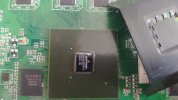
Using a early unit with horizontal RF sockets, thermocouple on SoC IC, wire coming through a specially-punched 3.5mm hole and cover fitted properly, unit not recording or playing back during test, fan set to 50%, ambient temp 20-20.5C throughout, HDD temps as reported by drive, figures after things had stabilised for >20 minutes [Edit: That's after they's been stable for 20 minutes.]
Standard unit
Fan blowing out: HDD 39C, SoC 61CFan blowing in: HDD 31C, SoC 62C
With my slot-in-HDD-carrier mod
Fan blowing out: HDD 39C, SoC 61CFan blowing in: HDD 31C, SoC 59C
So there you have it - having the fan blow air in results an 8C cooler HDD as tested and has no effect on the SoC.
Cutting a slot in the HDD carrier and the fan blowing air in does result in a small drop in SoC temp but not as much as I'd hoped.
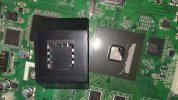
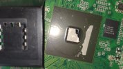
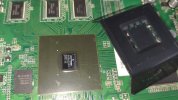
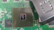
I've now done some experiments myself, using a 1TB HDR-FOX recently acquired (only 6½k hours on the HDD). My test probe is a thermocouple attachment for an ancient DMM resurrected for the purpose, which I was able to thread through the existing punch holes in the base and tape to the centre of the heatsink on the SoC (the SoC silicon will be substantially hotter than the heatsink, due to the thermal resistances (see spoiler) from the silicon to the heatsink through the encapsulation and any bonding, but without knowledge of the resistance and the actual power dissipation it is not possible to calculate the actual silicon temperature).
Heat moves in a similar way to a fluid or even electricity, from a source to a sink. The temperature difference between the source and the sink is analogous to pressure or voltage difference, and the rate at which heat is conducted is analogous to conductance (the inverse of resistance). Consequently, characteristics of the heat flow can be calculated using Kirchoff's Laws reapplied from electrical circuits to heat circuits, which (essentially) say that (in the steady state) the sum of the currents (or heat flow) into a circuit node is equal to the sum of the currents out of the node.
Thermal resistance is quoted in units of °C/W (degrees Celcius per Watt), in other words how great the temperature difference has to be to drive one Watt of thermal power through that item, and each component in the heat path can be stacked up in series or parallel (or combinations) just like resistors or water pipes. Usually we are only dealing with the series path from the heat source (the actual silicon of a chip), through the chip's encapsulation, to the heatsink.
The chip's datasheet will declare the thermal resistance from the chip to the surface of the encapsulation, and then the heatsink has a quoted (or calculated from standard formulae) thermal resistance from the contact area to free air and/or forced air. Add the two together and you get the total thermal resistance from the chip to free/forced air, and therefore the temperature difference between ambient and the silicon (presuming you know how many Watts the silicon is dissipating). There also needs to be a consideration for the thermal resistance of the bonding between the chip encapsulation and the heatsink – whether that be a shim of thermal grease (good conduction) or just touching contact (poor conduction).
In parallel with the heat path from silicon to heatsink, there is also the heat path from silicon to PCB. On a through-hole leaded component this path tends to have comparatively high thermal resistance, because the heat has to pass along the fine electrical bonding wires (or the high-resistance encapsulation) to the lead frame (as the metal pins are called), then through the lead frame to the solder pads on the PCB. Typically the component body is not in direct contact with the PCB. However, surface-mount components are in direct contact with the PCB, and high-power components frequently enhance that contact using metal thermal bonding soldered directly to the PCB under the package (by using industrial reflow soldering). Combined with a PCB deliberately designed to sink the heat away from the chip (by using the copper in a "ground plane" as the heatsink), this is why even high power devices can be so remarkably tiny when in surface-mount packages.
The aim is to keep the silicon below its maximum permitted operating temperature under all conditions of peak power and ambient temperature. Even below the maximum specified temperature, expected working life increases rapidly for every degree reduced below that. For the industrial production engineer, there is a trade-off to be struck between product life and the cost of adding more cooling (in terms of both parts cost and assembly cost).
How much is enough? Adding a fan (to provide forced air) is not only expensive, it is also an extra point of potential failure and production rejects. Given that I have three HDR-FOXes operating practically 24/7 for the last ten years, I would hazard a guess that Humax got it right (not necessarily from our point of view, but certainly theirs).
Note that the readings are uncalibrated and for indication only. The DMM/thermocouple recorded an ambient temperature of 20°C before I started, and it won't have changed much. fan* is set to 40%, HDD temperature readings are through sysmon*.
* Custom Firmware packages.
System load: Idling (BBC ONE HD or BBC TWO HD playing live).
Fan in suck mode (normal for V1):
HDD 44°C
SoC 67°C
Fan in blow mode (normal for RE):
HDD 37°C
SoC 67°C
With lid off:
SoC 57°C
Adding load of iPlayer playback, or even two HiDef recordings while playing a third, didn't make a noticeable difference to the SoC temperature. Adding HiDef decryption (hardware assisted) to that took it up from 67 to 70°C.
With a CPU fan arranged very similar to this: https://hummy.tv/forum/threads/replacement-t2.10196/post-155156, the thermocouple temperature reading comes down from 67 to 52°C (which went up to 56°C while decrypting), a useful 15-degree reduction in the SoC operating temperature (which should track).
Last edited: