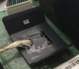
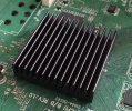
I discovered (when one fell off recently) that the heat-sink in the centre of the HD-Fox T2 main board is actually fixed at the four corners with what appeared to be some industrial double-sided tape but might just have been glue baked for nearly a decade. The lack of a heat-sink didn't have any short-term effect, but possibly there are many units operating marginally with poor contact between the chip (with its layer of heat-sink compound) and its heat-sink. Without disassembling again, I assume that the heat-sink is protecting the SoC and that a similar arrangement applies to HDRs since the same chip is used.
-
 The forum software that supports hummy.tv has been upgraded to XenForo 2.3!
Please bear with us as we continue to tweak things, and feel free to post any questions, issues or suggestions in the upgrade thread.
You are using an out of date browser. It may not display this or other websites correctly.
You should upgrade or use an alternative browser.
You should upgrade or use an alternative browser.
Replacement T2
- Thread starter PerryM
- Start date
So I installed 'fan', set it to 60% (barely audible) and so far so good. It would thus appear that the standard fan mode is set to come on at too high a temperature for my box for whatever reason. The great news for me is that the fan is definitely working.
Thanks again for all the support.
Thanks again for all the support.
Black Hole
May contain traces of nut
I can help with that.I assume that... a similar arrangement applies to HDRs since the same chip is used.
Black Hole
May contain traces of nut
I can help with that.
I had a look at the mechanical mounting on a faulty one, but the fixing appeared strong and I didn't (at that occasion) go so far as to force the issue.
Is the HDR heat-sink clamped or does it just sit on the board (like the first example in this useful list of attachment methods)?
everthewatcher
Forum Supporter
There's no clamping method and there seems to be no movement so I've assumed it's suck on the chip, in which case removal will probably go badly if it's an exposed die.Is the HDR heat-sink clamped or does it just sit on the board (like the first example in this useful list of attachment methods)?
I've a hedgehog-style heatsink here that would glue nicely onto the existing one but I've seen no need to do so yet.
Black Hole
May contain traces of nut
No reason to suppose that - everything else is packaged, and I can't imagine it would be economic to make an exception for the SoC. It would need to be packaged to be compatible with normal pick-and-place machines.if it's an exposed die.
I thought there were enough photos about to consult, eg:Is the HDR heat-sink clamped or does it just sit on the board
...but if you need more:

(the "string" is the cotton cover for my thermocouple, cellotaped to the heatsink)
Interestingly (or not) that's an entirely different heat-sink from the HD-Fox one, which is more finny, like the ones shown in the link that I posted above. Also interestingly, "finny" is a word in the browser's spell-check dictionary, but "heatsink" isn't!
So perhaps it was necessary to use a fancier heat-sink in the HD, whereas a simple flange sufficed in the HDR because of the residual ventilation due to the disk fan.
So perhaps it was necessary to use a fancier heat-sink in the HD, whereas a simple flange sufficed in the HDR because of the residual ventilation due to the disk fan.
Black Hole
May contain traces of nut
bottletop
Active Member
There's no clamping method and there seems to be no movement so I've assumed it's suck on the chip, in which case removal will probably go badly if it's an exposed die.
I've a hedgehog-style heatsink here that would glue nicely onto the existing one but I've seen no need to do so yet.
I didn't realise the HD-FOX uses a proper heatsink. In that case I will probably replace the crappy heatsink on my HDRs with a finned or headgehog heatsink in the future.Interestingly (or not) that's an entirely different heat-sink from the HD-Fox one, which is more finny, like the ones shown in the link that I posted above. Also interestingly, "finny" is a word in the browser's spell-check dictionary, but "heatsink" isn't!
So perhaps it was necessary to use a fancier heat-sink in the HD, whereas a simple flange sufficed in the HDR because of the residual ventilation due to the disk fan.
Edit: after see the next 2 comments, maybe this isn't a good idea!
Last edited:
Black Hole
May contain traces of nut
Don't. As noted above (or in one of the other concurrent threads) the finned heatsink is not very efficient without forced air (and these fins are only about 4mm apart). The HDR-FOX heatsink (having a larger effective surface area) may well have a lower thermal resistance to free air.I didn't realise the HD-FOX uses a proper heatsink. In that case I will probably replace the crappy heatsink on my HDRs with a finned or headgehog heatsink in the future.
everthewatcher
Forum Supporter
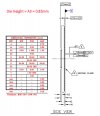
Bad choice of heatsink there - that style needs forced airflow plus it's mounted horizontally so the effective thermal resistance will be much higher than the figure the manufacturer gives. The one used on the HDR is called a heat spreader and is a much better choice with no forced or convection airflow.For reference (the HD-FOX heatsink), a standard extrusion
everthewatcher
Forum Supporter
Flip chip BGA , where the back of the die is exposed like this Celeron Mobile package on WP.No reason to suppose that - everything else is packaged, and I can't imagine it would be economic to make an exception for the SoC. It would need to be packaged to be compatible with normal pick-and-place machines.
Ezra Pound
Well-Known Member
everthewatcher said : if it's an exposed die.
Bottletop's post here shows an exposed dieNo reason to suppose that - everything else is packaged, and I can't imagine it would be economic to make an exception for the SoC.
Internal Temperatures (SoC)
Using a early unit with horizontal RF sockets, thermocouple on SoC IC, wire coming through a specially-punched 3.5mm hole and cover fitted properly, unit not recording or playing back during test, fan set to 50%, ambient temp 20-20.5C throughout, HDD temps as reported by drive, figures after...
Last edited:
Black Hole
May contain traces of nut
Fair enough. So why is there so much clearance under the "heat spreader"?
everthewatcher
Forum Supporter
Not sure what's being asked here. Between heatsink/spreader and BGA substrate? If yes then surely it just means the die is thicker than the depression in the spreader.Fair enough. So why is there so much clearance under the "heat spreader"?
Black Hole
May contain traces of nut
So far as I can make out (digital calipers) there is about 1mm gap between the base of the spreader and the PCB, and the central depression (presuming it is the same 0.8mm thickness all over) adds another 0.8mm to that. 1.8mm seems a bit thick for a PCB-mounted die.If yes then surely it just means the die is thicker than the depression in the spreader.
Do you mean that? I thought BGAs are ceramic (or am I out of date?).
Black Hole
May contain traces of nut
Belay all that, posts in the other thread explain all (click through for pictures):
Pictures after removing the very sticky double sided heatsink adhesive.
The dental floss method works well for initial separation of the adhesive tape. Then it's gentle srubbing using fingernails or plastic spatula type tool.
As the adhesive was still very strong, I doubt it has suffered overheating.
Overheating will usually make the adhesive tape brittle - which this wasn't at all.
For anyone worried about using the dental flossing method - try it on something else first.
Eg anything that as has been mounted with strong adhesive tape.
Super! That explains a lot. So what I thought was a thick adhesive layer holding the spreader to the PCB is actually the BGA substrate.


