Start Up Fails When HDD Connected

But it might be possible to desolder and lift just the control pin and improvise the necessary drive circuit (a small 1k resistor soldered to the control pin and connected to Fin for disable or VCC for enable?).
I still don't see the point (and I have U52 off now anyway). I have established the voltages at the nodes relevant to the control pin are correct compared with a known working unit, so the currents must also be correct. There is nothing to be gained by subjecting U52 to abnormal drive currents, other than the possibility of characterising the defect.

The next hurdle is finding out whether U53 really is redundant!
 
Last edited:
Supposing this is a common failure on units exhibiting these symptoms, it's curious. The LDO is supposed to have over-current and over-temperature protection.
 
Supposing this is a common failure on units exhibiting these symptoms, it's curious. The LDO is supposed to have over-current and over-temperature protection.
Well exactly - voltage regulator ICs are quite capable of looking after themselves within their absolute max voltage ratings.

IME there are two ways of killing them: Over voltage on the input and pulling the output negative on devices that have a hard 0V connection. The latter is one reason why on devices with +/- supply rails you should always fit diodes across regulator outputs in case there's a short to the opposite rail as one regulator will always win the resulting tug-of-war.

Was it ever established whether the IC was shutting down itself or being shut down via the control pin?
 
The 'scope traces show the LDO not turning on enough when there is a load. It's too quick to be thermal limiting (and anyway that would be a shutdown), so that leaves current limiting as if the load were too great.
 
I have decided it is too risky to go to the trouble of fitting a salvaged part - I have some new ones being flown in next week.

The risk is that the salvaged part is damaged and would have to be taken off again - that risks damage to the main board which would then need to be repaired.
 
I have some new ones being flown in next week.
That's impressive! Before ordering, I asked how long before delivery and was told 2 days to process the order and up 5 days transit. I ordered Wednesday, had notification of shipment Thursday, and the FedEx van turned up this morning.

That's today's job sorted!
 
And the results are in...

I had no choice than to replace the LDO having taken it off, but as we had suspected that's not the cause of the fault. It's upstream of there, I should have looked before but the supply to the LDO is dropping as if current limited, so it looks like the SMPS is implicated.

Further upstream again is the PSU itself, but that has been replaced to no effect so I'm not suspecting that at the moment.
 
In another thread the non-ground voltages on the PSU connector were measured at 12.25V and 6.6-ish V, and this accords with what I recall.

Why does the PW808 PSU have a label on the edge of the PCB next to a large heat-sink for what I guess is the mains voltage oscillator of the main SMPS (3 pins - a transistor? can't ID it from online pix) saying "+5.8V 3.0A"? Is 5.8V what 6.6V becomes under load?

Why is there some on-board DC-DC converter in addition to the LDO regulators if a suitable input voltage is already being provided?

Also, there seem to be only 2 power diodes on the secondary side of the PSU, so is it just half-wave rectifying a centre-tapped transformer output to +6-0--6 and referencing -6 to ground? That would certainly make the electrolytics critical (++ripple).

And
...
Something to note is that a HDD with 5V current requirement greater than 1A would not be supported.
The SATA power cable is specified for 1.5A for each of the three pins providing 5V, but there doesn't seem to be any minimum requirement for the total power to be provided at any of the SATA voltages in the SATA specs.
 
Why does the PW808 PSU...
1) It's an unregulated rail. The +12V rail is regulated and as the load on it increases the unregulated rail voltage will rise.

2) There are several regulators dotted around the main board, some linear and some switch-mode.

3) There are two secondary supplies hence two rectifiers.
 
There are several regulators dotted around the main board, some linear and some switch-mode.
Yes, and there's 40V (or ±20V) generated for some reason. The PSU outputs 12.3V and 6.7V (the "6.7V" output varies somewhat, actually appearing to go up with increased load).


Investigation Update

I'm continuing to document this in the hope that many eyes might spot something – I'm pretty stumped at the moment.

U52 gets its input voltage from U22, which is an Alpha Omega AOZ1073AI 3A buck (voltage lowering) SMPS (equivalent datasheet). Pretty amazing, considering it's an 8-pin SOIC.
585A0E52-50A3-4646-89C8-B02A5255FAC3.jpeg
E111E9F4-E782-4E11-8BFD-D1F20D90AA92.jpeg
5CEBA569-25D3-4C67-903E-EF458DD0F7D9.jpeg
11058B9A-FCEE-4A5F-83EF-EAC381593D5E.jpeg

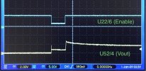
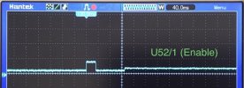
The bottom (yellow) trace is the 5V rail to the HDD. If you look at the trace for U52's input voltage (U52/2) you see it takes a dip just when U52 is supposed to turn on. The input voltage to U22 is OK (U22/2), but U22's enable pin goes low at the critical time (U22/6).

I don't know what's driving U22/6. I presume it's a micro I/O, but why should it turn off? It's weird. With the HDD not connected, the enable remains high.

For reference, below is for a "good" HDR, U22/6 and U52/4.
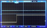
E4210072-9DC2-4B8A-A212-ADC617E4B886.jpeg

Having slept on the problem, I think the way forward is to lift U22/6 (the enable pin) and see what's what. Is the apparent shut-down for real, or is it some kind of back-drive? What if I tie it permanently high?

This is not clear though, there is still the restart to explain. The unit reboots the moment the HDD power comes up, and that could be the reason for the shut-down on U22/6 (although I would then expect the leading edge to be coincident with the trailing edge on U52/1). If I isolate U22/6 and pull it high, and the reset still occurs, I will have been looking in the wrong place!
 
Last edited:
Yes, and there's 40V (or ±20V) generated for some reason. The PSU outputs 12.3V and 6.7V (the "6.7V" output varies somewhat, actually appearing to go up with increased load).
In olden days a 40V supply would be for a varicap diode tuner. No idea what they're using these days.

The unregulated "6.7V" supply will go up with the load on the regulated 12V supply but should go down if the load is on it alone.

I'll go through the rest when my brain's working properly.
 
I'll go through the rest when my brain's working properly.
First thoughts: Is U22 enable being taken low due to something the HDD is causing to happen, or is it due to something that is expected to happen but doesn't. A say 500mA dummy load on the HDD +5V supply might be illuminating.
 
For the purpose of discussion, in what way illuminating? It would still be a fault, because the "good" HDR shows no such behaviour whether the HDD is connected or not. At first gance the PG pin doesn't appear to go anywhere. Nonetheless, it would be more convenient to work with a dummy load than keep plugging in a HDD.
 
For the purpose of discussion, in what way illuminating?
If it's happy with a passive load on the 5V supply it then it eliminates power draw as the cause of the enable line going low, and it would also eliminate the enable signal only remaining high if an HDD is actually sensed via something on the SATA data connection?
 
BA00BC0W... ordered, but estimated delivery up to 3 months!
Order for 10-off placed on eBay for delivery from China 10th April, with an estimated delivery 30th April to 28th June, arrived yesterday (1st May). Pretty damn good, but made redundant because I subsequently fast-tracked a batch from the States (Mouser). The transaction cost £2.74.

1619941309554.png

I've been distracted by other shizzle (new developments regarding J, and other commitments) so the investigation has gone quiet for the moment, but I have acquired a cheap USB 8-channel 24MHz logic analyser* (effectively an 8-channel 'scope for digital circuits, but relying on a PC for control and display) to ease monitoring of multiple circuit nodes simultaneously. I have yet to get to grips with it.

* Somebody somewhere came up with an FPGA implementation of what used to be a very expensive piece of kit, and now clones are all over the place for very little money. I knew about this some time ago, but the price wasn't low enough to make it a spontaneous purchase. When I was engineering for a living, a stand-alone Hewlett-Packard logic analyser (typically 32 digital channels plus four clock/triggers, even better if it had a couple of analogue channels as well) was the tool of choice and cost thousands of pounds. When the site closed down I "liberated" one (it was maybe 8"x20"x26" and weighed 20kg), but got unlucky and picked the one with a broken timebase :doh:. I don't expect the FPGA to have anywhere near the sophistication of a HP, but for hobbyist use anything is better than nothing.
 
Hewlett-Packard logic analyser (typically 32 digital channels plus four clock/triggers, even better if it had a couple of analogue channels as well) was the tool of choice and cost thousands of pounds. When the site closed down I "liberated" one (it was maybe 8"x20"x26" and weighed 20kg),
I can vouch for the weight of these things I had to take a HP1600A on a train to Edinburgh in the late 1970s / early 1980s to fault find some equipment, it had a large pouch attached to the top to hold all the logic pods, nice piece of kit for its day
 
nice piece of kit for its day
Judging from a google for "HP1600A" that looks a bit primitive compared with my recollections. 1631 rings a bell. I've just discovered I can buy a 1651A for £70... plus £140 shipping! Images have reminded me that what I half-hitched was a 16500.

I wasn't on that trip, but a couple of our guys went off on a site visit in a hired estate, loaded with analysers and whatever (including a protocol analyser which cost as much as a house), and rolled the car.
 
Back
Top