Start Up Fails When HDD Connected

In a related thread, I suggested, not entirely seriously
Some sort of small timer+relay circuit (as small as a circuit with 2 2-pole or 1 4-pole relay can be) could be interposed in the disk power cable to automate [the process of detaching and re-attaching the disk power around boot]. Actually you can get a 4-pole timer-on relay as a single unit, but at RS it's at least as expensive as a second-hand HDR-Fox T2, though if this listing on "an internet auction site" is to be believed that's 10x too much.
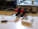
Other hack solutions: bypass the on-board supply and fit a 5V+12V brick with a SATA adapter, wiring its mains cable to the input of the power supply (CN1), or just a scrap 5V/1A brick wired in place of the LDO regulator (U52) o/p (SG Pipeline 2TB: 5V/0.55A, 12V/0.37A), as the 12V supply is not apparently implicated.

Then
I think there is a much easier solution, it seems to me that this is an inrush current problem, I.e. the hard disk is creating too big a current demand on start-up, (or the PSU can't cope as well as it used to), the U52 component can be made to limit this inrush current by adding a bigger value capacitor to the control pin (pin 1), see marked capacitor here :-
View attachment 5579
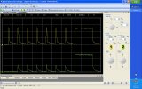
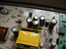
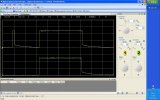
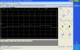
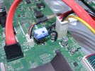
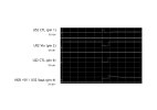
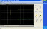
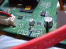
If so, this looks good in principle but ... If my sums are right the capacitor between pin 1 and ground has to be about 960μF per second of delay to reach 2V (of the steady state 2.9V) at pin 1 (assuming the current into pin 1 stays roughly as specified for 0A output). This could have to be some whacking capacitor, relative to the existing one which from the trace above (appearing vertical with 40ms timebase) must be less than 1μF, and even 5x the output capacitor for 0.5s delay. I suppose one could put 470μF, then 47, then 4.7, etc, across pin 1 and ground in parallel with the existing one to test.

Finally, OP of the original thread said that the resurrection instructions were followed, which would have included re-flashing the box: was that actually done? If some unexpected system management software action (ie, turning off U22) is implicated, could there be a firmware glitch?
...The supply to the HDD is unswitched on the 12V rail but switched on 5V, and the 5V supply turns on when the HDR-FOX comes out of the initial boot phase (indicated by the VFD "Cust FW #.##" turning off).
...
The VFD message is set by the /etc/init.d/S25banner startup script and reset by the settop program, which initiates discovery of the disk, in turn launched by /etc/init.d/S90settop. The documentation on the web for the 7405 power management function is based on a later Linux version (with /sys/power) but I think its statement that SATA is managed by Linux is still valid (some other hardware functions have Nexus APIs).

You can see what happens at startup in a kernel debug log posted in another thread (look for "brcm-pm", and also be aware that the log is from a faulty system where a kernel bug caused the disk not to spin up). This leads to another thought, that it could be useful to run up a problem system with a debug kernel to see if (a) the U22 turn-off still occurs (b) if so, what is logged for that action.
 
Last edited:
Can anyone see anything (on the HDR-FOX PCB) which looks like a power-on reset circuit? It's on page 21 of those circuit diagrams (a Maxim chip), but I haven't spotted anything similar.
 
I wonder where the HD-Fox T2 reset button leads? Sadly it's part of the front panel which makes it unclear whether it's handled locally (perhaps generating a short interruption to the power supply) or routed to the main board.

While I had the board, magnifying glass and light together, I found these ICs on the HD-Fox T2 main board:
  • U152, a 10-pin mini d-i-l package next to the main power connector and an inductor, label V59P823;
  • next back from the front, U153, EUP7996 1.5A DDR Termination Regulator;
  • next, by the ribbon connector to the power board (though it seems to have the SPDIF output too), U150, same as U152;
  • close by, U700, SOIC-8, label indistinct;
  • in the next column front to back, U621, U623: 2 x H5PS1G63EFR-S6C 64M x 16-bit DDR2 DRAM (ie 2 x 128Mbyte);
  • next U622, apparently labelled H5PS51G2FFR-S6C (no obvious matching spec), appears similar but must be something other than straightforward RAM (shadow RAM into which ROM is copied for speed?); the 4th location U624 is unpopulated;
  • at the back by the HDMI socket, U1650, NXP TDA9984A HDMI 1.3 transmitter with 1080p upscaler;
  • in the next column front to back, U551, SOIC-8 with indistinct label, similar to this but "0952" instead of "1444" and a slightly different top line; from the new pic below, it's a 24LC64 64K I2C 400kHz Serial EEPROM;
  • next to the SoC, a BGA package U222 with indistinct label;
  • the SoC, component ID presumably under the heat-sink (and, yes, Wilko imitation Bostik is an effective replacement for the failed sticky pads);
  • at the back, U1600, TDA19977 HDMI1.4 receiver (see here for thea possible rationale for U1600 and U1650 to augment the SoC's limited HDMI support);
  • next to it, U1652 and U1651 are BA00BC0WCP LDO regulators like U52 in the HDR;
  • in the next column front to back, behind the SoC, U1500 is a TSOP-8 or similar, label indistinct, and close by U1501 appears similar;
  • next, U151 is another BA00BC0WCP LDO regulator;
  • close to the TV SCART socket is U1250, STV6412A Audio/video switch matrix, apparently the device labelled "HDMI Xmit" in the Wiki HDR PCB pic but actually an analogue switch;
  • front to back on the far edge, U1532 is another LDO regulator, this time ST LD291501.5A very low drop voltage regulator;
  • U1530 is yet another LDO regulator, RichTek RT9183H Ultra Low Dropout 1.5A Linear Regulator (NB the supplier changes the version number in the datasheet URL, like -19 -> -22 and drops the old one);
  • finally, U1560 is the DVB demodulator Sony CXD2820R.
The story goes that Professor JBS Haldane was asked what characteristic of the mind of the Creator could be discerned from study of nature, and responded "An inordinate fondness for beetles". Asking a similar question about the HD-Fox T2 main board and its designers, we might say "An inordinate fondness for low dropout voltage regulators".
 
Last edited:
I did a similar exercise, but had not got around to compiling the results.

UPDATE: There are also components on the underside of the board we have not considered.

An inordinate fondness for low dropout voltage regulators
Definitely. I guess it might be possible to use the enable pin as a POR.
 
Last edited:
I’ll have a good read through this thread as I’ve been chasing-down the same (or a similar) fault with our HDR-Fox T2 for a few weeks now (since mid-Oct 2021). Fortunately, I have a fully-working spare PVR and have tried swapping the power board, the HDD and the front panel board to confirm the problem is with the main board.

Unplugging the HDD power connector solves the problem – which is that after the PVR has been in standby for a few hours, it goes through up to 11 start-up attempts (Humax splash screens) before the HDD runs-up, at which point it goes back into standby; it will then promptly come out of standby when commanded. So likely a temperature-related problem; to confirm, today, having been in standby for many hours I baked the PVR in the oven at 30 degrees C for 30 minutes before powering it up and it worked fine; conversely, later I left it in standby for a few hours in its usual location and it went through 9 start-up attempts when powered-up.

Otherwise, the PVR is performing absolutely fine. EPG-programmed recordings aren’t affected – the HDD runs-up 18 minutes prior ok. I did one check of a manually-programmed recording and the HDD ran-up ok at 3 minutes prior and the recording worked. One power-on timer event worked, with the HDD running-up ok 3 minutes prior, another was missed due to multiple start-up attempts.

I used my USB ‘scope in roll (chart recorder) mode to capture the behaviour of the 5V and 12V HDD rails when coming out of/going in to standby on the working PVR and have attached a grab. The horizontal scale is actually 6s/div with out-of-standby at 5s, in-to-standby at 30s. Timings were done with a stopwatch – why the Agilent ‘scope is actually capturing at 6s/div when it’s set to 5s/div is another problem for another day. I will repeat this test on the faulty PVR.

Earlier this year I easily fixed a warm-up fault on our 16” Grundig TV – a bulging 1000u/16V cap on the power board was confirmed as the culprit as a shot of freezer spray provoked the fault. This problem is a bit more challenging.

[Edited 10 Nov 2021 to change attachment from .pdf to .jpg]
 

Attachments

  • Good PVR startup + shutdown, 60s per 10 divs.jpg
    Good PVR startup + shutdown, 60s per 10 divs.jpg
    152.2 KB · Views: 23
Last edited:
Having read through this thread, not sure what conclusions were drawn by previous contributors as it seems to have gone cold. At this time, I reckon the problem I'm having is due to a dud cap - but which one? Results attached show the problem isn't confined to the HDD's 5V supply - the 12V supply is in trouble too. The attached pic shows the several attempts the PVR makes to come out of standby before the HDD finally runs-up.
 

Attachments

  • Faulty PVR startup.jpg
    Faulty PVR startup.jpg
    177.6 KB · Views: 23
Having read through this thread, not sure what conclusions were drawn by previous contributors as it seems to have gone cold. At this time, I reckon the problem I'm having is due to a dud cap - but which one? Results attached show the problem isn't confined to the HDD's 5V supply - the 12V supply is in trouble too. The attached pic shows the several attempts the PVR makes to come out of standby before the HDD finally runs-up.
Those are similar to what I found.
My scope is much simpler, an old Picoscope but your pic 2 was what I saw with the old caps, and your pic 1 in the previous post with the new caps.
I simply replaced any of the big caps on the PSU card that might have the high switching frequency present. I also took the opportunity to increase the sizes etc to boost the peak current capacity

Here are the details of what I ended up with.
 
Having read through this thread, not sure what conclusions were drawn by previous contributors as it seems to have gone cold. At this time, I reckon the problem I'm having is due to a dud cap - but which one? ...
If it works when it's warm but not otherwise, isn't a dodgy connection more likely, either a dry joint, or a small crack in the PCB, or :-( :-( some internal connection in one of the ICs?
 
as it seems to have gone cold.
In summary, AFAICR, the HDD supply is turned on by the SoC but the control signal mysteriously goes away... but as there is no visibility inside the SoC I have no idea why. I assume there is some kind of status monitoring at another SoC input, and to make reasonable progress would require reverse-engineering the entire PCB to obtain a full circuit diagram instead of just the targeted excerpts derived so far.

It's gone cold because I don't feel I can make inroads without a great deal of time spent, and that will require greater priority than I can give it. Anyone willing to put in the effort and produce the circuit digram would aid the analysis.
 
Those are similar to what I found.
My scope is much simpler, an old Picoscope but your pic 2 was what I saw with the old caps, and your pic 1 in the previous post with the new caps.
I simply replaced any of the big caps on the PSU card that might have the high switching frequency present. I also took the opportunity to increase the sizes etc to boost the peak current capacity

Here are the details of what I ended up with.

Thanks for your comments and I have read your thread. However (as I said) I tried the power board from the fully-working spare PVR and it didn’t fix - so I don’t think that’s where the problem lies.

I had hoped it was – as was the case with the Grundig TV I fixed. The attached shows that there were actually 3 bulging (domed) caps. I used my Peak ESR70 Atlas meter on the 1000u/16V cap I removed and its replacement (ESR = equivalent series resistance). From my notes: C2012 (G-LUXON LZ 105°C) removed; measured 645u/0.74R reducing/increasing to "* In-Circuit *" or 400u/4.7R after chilling with freezer; TAICON 105°C (PW) replacement measured 983u/0.1R reducing/increasing to 964u/0.12R when chilled.

Incidentally, good practice would have been to replace all 3 caps, but by then I'd found the same model TV on eBay at a good price, so the repair became an academic exercise and the original TV a source of spares for the future.
 

Attachments

  • Original's 3 suspect caps.JPG
    Original's 3 suspect caps.JPG
    323.4 KB · Views: 23
If it works when it's warm but not otherwise, isn't a dodgy connection more likely, either a dry joint, or a small crack in the PCB, or :-( :-( some internal connection in one of the ICs?

Well, those are all possible causes.

However, at least conventional-style electrolytics (see the pic of the dodgy ones in the Grundig TV) are always the first port of call, especially if they are located near a heat source (such as a heatsink) which will accelerate their “drying-out”. Heat and their chemistry are the issues here. That said, I’ve no personal experience of the SMD electrolytics of the type that are liberally sprinkled over the PVR’s main board failing likewise - but I bet they do, and my money is on it being one of these. Silicon is generally orders of magnitude more reliable than electrolytic caps.

With the Grundig TV, my wife (it’s located in her boudoir) was complaining that Freeview reception was breaking up for the first few minutes after switch-on.
 
In summary, AFAICR, the HDD supply is turned on by the SoC but the control signal mysteriously goes away... but as there is no visibility inside the SoC I have no idea why. I assume there is some kind of status monitoring at another SoC input, and to make reasonable progress would require reverse-engineering the entire PCB to obtain a full circuit diagram instead of just the targeted excerpts derived so far.

It's gone cold because I don't feel I can make inroads without a great deal of time spent, and that will require greater priority than I can give it. Anyone willing to put in the effort and produce the circuit digram would aid the analysis.

Thanks for your comments. You focussed your attention on the HDD’s +5V supply. Did you have any issues with its +12V supply, do you recall – like I have found? At one point you said that the input to the buck converter U22 which feeds U52 “is OK” (as per the ‘scope trace). Your schematic suggests this might come directly from the power board – I’ll check this. According to your schematic, the input to U22 goes via a switch to become the HDD’s +12V.

Expecting to go down the same route as you I attached some monitor wires to U52’s input and control pins (at my age, good light, a magnifying glass, flux remover and a pic all necessary to confirm no bridging shorts). That was probably unnecessary given what I found with my initial roll-mode ‘scoping of the faulty PVR. I will take a closer look at the rising edges of the HDD’s supplies when the boot attempts occur to see if it matches what you found on the +5V.

That the HDD’s +12V is in trouble suggests an upstream problem. I am currently devising a practical strategy for checking the main board’s electrolytics (one of which is the likely culprit, in my view) while still keeping the faulty PVR in daily use. Today I’ll check the power board’s outputs at startup in case there are any clues here – but I’ve already tried another board from a fully working PVR, of course.

Also, was the fault with your PVR a hard one – did it eventually run-up the HDD, given enough attempts? It seems my PVR takes no more than 11 goes (I’m counting each time).

Finally, a close visual inspection of the main board’s SMD electrolytics might pay dividends – but they don’t have the characteristic “vent creases” of conventional electrolytics, so I’ll have to research their construction.
 

Attachments

  • Vin + CTL monitor wires added to U52.JPG
    Vin + CTL monitor wires added to U52.JPG
    327.2 KB · Views: 28
In the case I was researching, no issue with the +12V that I recall. As the symptoms were typical of several reports of failures, I presumed they all had the same cause.
 
I’ve attached some further measurements on my faulty PVR. These examine the 12V and 5.8V outputs* from the power board. I’ve compared these with the 12V and 5V HDD supplies under fault-present, and fault-not-present conditions (as described in the pic titles). For ease of reference I’ve attached again the (now retitled) pic from post #67.

Those power board rails are solid under the fault condition, which is consistent with having tried another power board from a fully working PVR to no avail.

I also examined the rising edges of the HDD supplies on a failed reboot attempt and found the same “stepping” on the 5V HDD supply that BH did.

*As per the silk-screening adjacent to the power board connector – but, as noted previously, the 5.8V actually rises to 6.6V (and above) between an out-of-standby command (pressing the front panel button) and 11s after the HDD supplies turn off, ie some 24s after an in-to-standby command (pressing the front panel button again). That seems a bit odd, but is not significant, I think. The silk-screening indicates multiple pins of the connector are used for ground and the rails (which is common practice) – there are no “sense” wires; these provide a PSU with a low-current “sniff” of the voltage at a remote point to force it to up its output to ensure the target voltage is achieved at that point under load conditions - ie compensating for the voltage drop along the wire delivering the current. I wouldn’t expect to see this technique in a consumer product like this; I first encountered it in the behemoth that was the BBC-designed-and–built EP5/512 studio vision mixer of the ‘70s: bbceng.info/EDI%20Sheets/10206.pdf

[Edited 11 Nov 2021 after spotting that change in 5.8V rail and HDD power off don't coincide.]
 

Attachments

  • Good PVR, HDD 12V+5V, 60s sweep, sby off 5s, sby on 30s.jpg
    Good PVR, HDD 12V+5V, 60s sweep, sby off 5s, sby on 30s.jpg
    152.2 KB · Views: 20
  • Faulty PVR, power board 12V+5.8V, 60s sweep, sby off 5s, good startup, sby on 30s.jpg
    Faulty PVR, power board 12V+5.8V, 60s sweep, sby off 5s, good startup, sby on 30s.jpg
    164.3 KB · Views: 19
  • Faulty PVR, power board 12V+HDD 12V, 60s sweep, sby off 5s, bad startup.jpg
    Faulty PVR, power board 12V+HDD 12V, 60s sweep, sby off 5s, bad startup.jpg
    165.5 KB · Views: 18
  • Faulty PVR, power board 5.8V+HDD 5V, 60s sweep, sby off 5s, bad startup.jpg
    Faulty PVR, power board 5.8V+HDD 5V, 60s sweep, sby off 5s, bad startup.jpg
    166.3 KB · Views: 19
  • Faulty PVR, HDD 12V+5V, 100ms per, failed startup attempt.jpg
    Faulty PVR, HDD 12V+5V, 100ms per, failed startup attempt.jpg
    175.6 KB · Views: 19
Last edited:
I now have a plan for tracking down the suspect electrolytic using a can of freezer - but before I go down that route, I’ll take a closer look at the timing wrt the HDD’s 5V rail of that troublesome pulse at U22’s enable pin (see BH's earlier work in this thread).

I’ve attached a zoomed-in version of the last pic in the previous post which shows the HDD’s 5V ramping-up at a sluggish dV/dt compared with the HDD’s 12V. I’m wondering whether the CPU has said “Nah, you’re not getting to 5V quick enough, mate – try again.” Could it be simply that the 100u/16V across U52’s output has dropped in value? That would be consistent with it all coming good with the HDD disconnected.

As with the Grundig TV, give it a minute or two to warm up and its value increases (and ESR decreases) and it's good-to-go; the PVR then boots ok.

[Edited 12 Nov 2021 to add following.]

I'll take that closer look if necessary, but the quickest way to prove my theory is to solder another cap across the suspect one and see if that fixes the problem. With hindsight, that would have been worth doing from the get-go, given all the evidence. Surely it must be that cap ...but Murphy is probably watching! I have a 220u/16V from the spares drawer, ready to go tomorrow morning (checked as 232u/0.26R on the ESR70).
 

Attachments

  • Faulty PVR, HDD 12V+5V, 100ms per, failed startup attempt, zoomed-in to 1ms per.jpg
    Faulty PVR, HDD 12V+5V, 100ms per, failed startup attempt, zoomed-in to 1ms per.jpg
    176.2 KB · Views: 11
Last edited:
Not the cap across U52's output - adding another made no difference (but had to try). To be continued...
 

Attachments

  • Cap added across U52's output.JPG
    Cap added across U52's output.JPG
    326.4 KB · Views: 24
  • Like
Reactions: /df
Thought I'd confirm BH's waveforms on page 3 of this thread, so added monitor wire to U22 pin 6. Also sanitised the the HDD supplies monitoring. Then tried unplugging HDD and adding dummy loads to HDD's supplies (eg 20R across 12V = 600mA; 4R7 across 5V = 1.06A) ...and reboot problem goes away.
 

Attachments

  • Confirming BH's findings.jpg
    Confirming BH's findings.jpg
    126.5 KB · Views: 14
  • CTL (pin 6) monitor wire added to U22.JPG
    CTL (pin 6) monitor wire added to U22.JPG
    326.7 KB · Views: 14
  • Sanitised HDD supply monitoring.JPG
    Sanitised HDD supply monitoring.JPG
    324 KB · Views: 14
  • Dummy loads.JPG
    Dummy loads.JPG
    336 KB · Views: 14
  • Faulty PVR, HDD 12V+5V, good startup, with 4R7 load on HDD 5V 20R load on 12V, HDD+SATA connec...jpg
    Faulty PVR, HDD 12V+5V, good startup, with 4R7 load on HDD 5V 20R load on 12V, HDD+SATA connec...jpg
    165.5 KB · Views: 13
I deployed the can-of-freezer strategy this morning by firstly baking the faulty PVR in the oven at 30 degrees C for 30 minutes. As found previously, it then booted ok first time (nice and warm).

I used the freezer on the accessible areas of the main board (some are hidden underneath the HDD). I tried the electrolytics, the crystals, various silicon, all without provoking the no-boot fault (the PVR was still warm enough to boot from standby ok each time) ...until, that is, I chilled the area around U24, an Si3458DV N-channel Mosfet transistor* and the nearby 2N4401 NPN bipolar transistor (both SOT-23 packages) and bingo! – the fault returned big-time (10 or more attempts).

So it’s likely it's one of these that’s dud (I don't think it's the 4u7/35V electrolytic as I’d separately targeted it earlier with no luck). I repeated the test (...back in the oven) to confirm my findings. Assuming my findings hold-up, the next step is to narrow down which transistor is the culprit. I hope it’s not one of the smaller components nearby (unlikely, I think). I may try resoldering the suspect transistor first before replacing it. A for-spares/repair PVR is on its way, thanks to eBay.

[Edited 16 Nov 2021 to add following and second attachment.]

I used a couple of Hellermann sleeves to thermally isolate the other components, applying pressure to form a seal when squirting freezer on the 2N4401; chilling this consistently causes the failure-to-boot problem - until it has had time to warm up, when the boot will succeed and the HDD will run-up ok.

[Edited 21 Nov 2021 to add asterisk and following.]

U24 isn't the device described above - see post #91
 

Attachments

  • Getting close....JPG
    Getting close....JPG
    324.1 KB · Views: 36
  • Thermal isolation.JPG
    Thermal isolation.JPG
    331.1 KB · Views: 30
Last edited:
Back
Top