Faulty Preamp PSU Caused Humax Reception Problems on Some Muxes

Easier said than done as the preamp connections are clamp-and-screw type, unfortunately.
I think I'd be replacing anything that doesn't have F connectors. I use the Proception 10dB dual output masthead amp. which is readily available from the likes of Toolstation and it's £13 currently. The single output is cheaper (beware the pictures are the wrong way round on their website).
a bit of an indulgence, but invaluable when trying to troubleshoot reception issues
Do you mind me asking where from and how much?
They don't exactly go out of their way to tell you where to buy one, so perhaps Promax et al have forced them out.
I only found one for sale second-hand and that was £300.
(The bloke who put my new aerial up had a Labgear I think).
 
I think I'd be replacing anything that doesn't have F connectors. I use the Proception 10dB dual output masthead amp. which is readily available from the likes of Toolstation and it's £13 currently. The single output is cheaper (beware the pictures are the wrong way round on their website).

Do you mind me asking where from and how much?
They don't exactly go out of their way to tell you where to buy one, so perhaps Promax et al have forced them out.
I only found one for sale second-hand and that was £300.
(The bloke who put my new aerial up had a Labgear I think).
I bought the last one on eBay at £299.95, new (I sold my old Maxpeak about a year ago for £150 - see pic). Designed and manufactured in Sweden with good documentation and likely good support too, it stood out from all the Chinese stuff and the cheaper "finders". Until I read the manual I was put off by mention of it being "made for both analog (dBuV) and digital DVB-T/T2-COFDM" but they just mean the type of display, not analogue as in analogue TV channels.

A bonus is that it might help me troubleshoot a problem with the remote light switch I installed in our garage some ten years ago. It worked fine until recently and I've found that as long as the TX and RX are within 50cm it still does, so either low RF from TX or low RF gain in RX. The frequency spectrum display extends down to 46 MHz so I might see something of the 315MHz RF link used by the remote switch. I've already changed the RF transistor and resonator in the TX (other pics), so next up is the first RF transistor in the RX.
 

Attachments

  • 315554528_3328000500771267_4395062673292399452_n.jpg
    315554528_3328000500771267_4395062673292399452_n.jpg
    310.9 KB · Views: 7
  • TX module 1.JPG
    TX module 1.JPG
    313.6 KB · Views: 7
  • TX module 2.JPG
    TX module 2.JPG
    311.5 KB · Views: 7
You say that your antenna is 25 years old which would make it pre digital switchover and the analog type where the driven element is a folded dipole compared to a dipole with a miniature transformer for impedance matching, “digital” antennas also have a very large reflector on the back with the cable running through the reflector before going down the pole, they also reject signals above Chanel 48 which are now used for mobile phone signals. Try a low-pass filter inline with your amplifier input which rejects Chanels 49-68.
 
There’s no need to be obnoxious in your replies to people. For your information I did read all the replies before posting. A low-pass filter should be in circuit the whole time and as a previous respondent has said all your connectors should be F-type. You haven’t said whether your antenna has a folded dipole or a dipole for the driven element.
 
You say that your antenna is 25 years old which would make it pre digital switchover and the analog type where the driven element is a folded dipole compared to a dipole with a miniature transformer for impedance matching, “digital” antennas also have a very large reflector on the back with the cable running through the reflector before going down the pole, they also reject signals above Chanel 48
Thanks for your comments, and welcome to the group. I still have the spec sheet for the Antiference Extragain range (I have an XG14A - Group A) which states that "Maximum signal transfer from aerial to cable is guaranteed with tuned baluns and resonators". I think that the balun is the transformer you refer to, but it's all done with PCB traces at UHF frequencies: "The Antiference PCB Balun not only provides improved impedance matching to your cable but also reduces the effect of impulse noise on digital reception". So "digital-ready", it would seem. I will check my old notes to confirm when it was actually installed but it is almost certainly overdue replacement (another reason for having a meter again so that I can check the performance of the new one).
 
You haven’t said whether your antenna has a folded dipole or a dipole for the driven element.
The dipole is an X type, rather than a folded one. Please explain "a dipole for the driven element". I can easily restore the LTE filter as it does have F-connectors.
 
There’s no need to be obnoxious in your replies to people.
He wasn't. He was just pointing out that it had already been tried.
A low-pass filter should be in circuit the whole time
A group A aerial isn't going to pick up very much at channel 49+. It has its own low-pass filter by nature of its design.
 
He wasn't. He was just pointing out that it had already been tried.
I suspect he/she read my pre-edited version, in which I remarked that seemed weird to chime in as a first post on this forum having only just signed up, apparently not having read what went before. Not a good way to introduce yourself, and only obnoxious if you choose to read it that way. Reminds me of somebody...

Being welcome doesn't come into it.
 
The dipole is an X type, rather than a folded one. Please explain "a dipole for the driven element". I can easily restore the LTE filter as it does have F-connectors.
the driven element is that part of the antenna that the cable is directly connected to, behind it you have a reflector and in front you have directors (the length and spacing of the directors is critical), a folded dipole as a driven element has the ends folded back and it is to those ends you connect the cable, a normal dipole has the cable connected to the middle and not the ends.
 
Why would you go for anything but a group A if using CP? You will get more gain, all other things being equal. There is no point in having a group K.
 
Why would you go for anything but a group A if using CP? You will get more gain, all other things being equal. There is no point in having a group K.
Antiference (a brand I trust) has a rather limited range these days. The RX20A has a forward gain of 14.5dBi, the XG16EW's is 17.2dBi. Seems the only Group A in the XG range is an XG8A (14.5dBi).
 
If you use the custom firmware, you can infer it from the nugget tuners.dump command, which tells you which tuner is recording to which file.
Are there any other useful nugget opions that don't appear in the help inormation?
Code:
 nugget
nugget <command>
  ping             - Test nugget connectivity.
  status           - Show nugget status and version.
  schedule.load    - Load recording schedule from disk.
  schedule.save    - Save recording schedule to disk.
  schedule.slot    - Update timers for schedule slot.
  schedule.db      - sqlite3 database handle info.
  schedule.epg     - Display EPG information for slot.
  schedule.timers  - Show internal timers.
  cryptokey        - Set or display encryption key.
  recordings       - Show in-progress recordings.
 
Are there any other useful nugget opions that don't appear in the help inormation?
Usefulness is subjective, but there are "schedule.entry N", and "schedule.timers.csv" and "quit". There are a couple of others but unless you know what you are doing (I don't) they really are of no use.
 
Al the main 6 muxes at CP are from the same antennas and have the same, nominal, effective radiated powers and pattern (there are minor, and I mean minor variations with frequency of course). All six should be received at near-equal level.

My gut is saying there's cancellations and reinforcements of the different frequencies occurring to give such a measured level variation in levels.

Woking is probably not line of sight to CP so the signals will be diffracted which can give rise to that. As may reception through trees (deciduous leaf sizes matching certain wavelength). Wolfbane will provide path profile plots based on postcode centre. Note that Reigate is now (since the 700 MHz clearance) in a single frequency network (SFN) with CP for those six and, although the 'other polarisation' may contribute something into the reception pot in Woking.

CP Main vs Reserve antenna working (reserve being lower) would change the received signal patterns (as well as having a different radiation pattern / frequency due to the design and necessary location.

Local TV is on a much lower level off one of the tower legs; but uses a more robust transmission mode that (IIRC) is equivalent to a 10dB power gain?

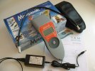
With cancellation / reinforcement (sometimes known as 'standing waves') antenna positioning is crucial to get as near to equal received levels as possible. Raising the antenna higher/lower, crabbing left/right and fore/aft (always pointing the aerial to the transmitter) should find the 'sweet spot'. A spectrum analyser type display that professional installer meters have will help to achieve this. The meter being purchased seems to offer that, or a quite similar, feature from a quick scan of the manual.

This is not something most would be advised to attempt on a rooftop (thinks Rod Hull) and is maybe best left to the professionals. You may possess the necessary safe access equipment and skills though?

Justin of ATV aerials in Sheffield favours the Yagi 18 he sells as being better built and more robust than any x-element design https://www.aerialsandtv.com/product/yagi-18a-aerial
He also sells the XB10A and XB16A - but I'm not sure you really need the small extra gain over the Yagi 18.
 
Back
Top