How To Prepare a "Sans-19" HDMI Lead
[NB: This should also apply to making an HDMI lead that isolates CEC on Pin 13. Pin 13 is three away from Pin 19 on the same side, fourth in from the end.]
While exploring, I almost destroyed a "good" HDMI lead which had metal screening in the plugs, and it was much easier modifying a not-so-good lead without the metal screening. It's not obvious which is which at the outset, but if you start with a really cheap HDMI lead it probably won't be screened. If it's anything to go by, the screened plugs are quite chunky and square, whereas if there is clearly not much rubber around the raw connector it probably isn't screened.
On the other hand, if you have a weak TV signal, you probably do want screened plugs in your HDMI lead...
I tried breaking into the cable itself, but that meant disturbing the cable braiding and then the foil screening beneath, and then trying to identify which conductor is hot-plug-detect. That's how the first lead nearly bit the dust – I decided pursuing that approach was too risky.
The photo shows which is Pin 19 (see arrow).
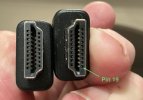
I'll describe modifying a plug with a screening shell, because without the shell all you have to do is ignore the steps involving it. For making good, it would be ideal to have some self-amalgamating tape* (see below) to hand.
What worked for me was to remove the rubber housing by slicing it all along one side (including the cable strain relief) with a sharp craft knife. Mind your fingers!
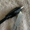
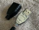
Now the two halves of the shell separate, having eased the crimp open around the cable (tease it with a fine screwdriver, open it out straight with pliers more than shown – for reassembly). There are latches near the connector end which need teasing too.
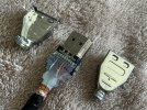
The moulded insulation near Pin 19 can be eased up, exposing the solder joint (see arrow). Note this is on the "fat" side (with 10 contacts) not the "narrow" side (with 9 contacts).
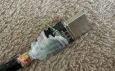
Rather than try to get a soldering iron in there, I simply used an approach we used to rework PCBs: make two parallel cuts across a track and remove the copper in between. That meant the track was definitely cut. With the point of a sharp knife, press hard to cut through the contact at the connector end and at the wire end, and remove between the cuts (see the ellipse).
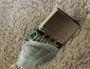
Press the insulation back, then replace the shell and re-crimp it around the cable. Be careful which half goes where, they only fit one way around as per the D shape of the connector. Then the rubber housing can be replaced. To seal it up, I simply wrapped if with self-amalgamating tape. And then finally added a label with some yellow heat-shrink and a fine-point permanent marker (Sharpie).
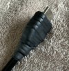
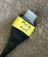
To be absolutely clear (seems obvious, but...): you only need to do this at one end of the cable, and it doesn't matter which way around you use the cable.
*
Self-Amalgamating Tape
Vital supplies in the tool kit of any DIY-er, self-amalgamating tape is a strip of natural unvulcanised rubber which can be wrapped around things and sticks to itself, and eventually merges into one solid layer. Stretch it as it goes on to produce a tight clamp and improve amalgamation (and a thinner layer). So that it doesn't amalgamate on the roll, it has a backing strip separating it (which you remove – either as it comes off the roll, or cut a length and remove it before application). It can be easier to handle if a length is cut first.
It will seal low-pressure plumbing (waste pipes), but don't expect it to seal a leak in a mains feed. Great for making rubber handles on tools.
Self-amalgamating tape used to be quite expensive, but now quite often found in Aldi called "stretch repair tape" and also available at Screwfix etc etc (for a bit more money). Buy some when you see it. If it doesn't have a separator strip, or isn't stretchy, or feels sticky on one side rather than grippy on both, it isn't self-amalgamating tape.