Newcoppiceman
Active Member
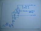
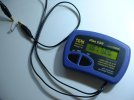
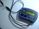
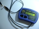
Confidence was high that the 2N4401 was dud – but started to wane when its junctions were checked out of circuit with a DMM and nothing abnormal was found. Sure enough, after transplanting the one from the working PVR it didn’t fix the fault.
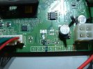
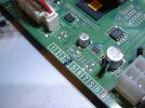
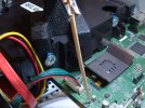
Attention has returned to the nearby electrolytic over which I placed a 1” long Hellermann sleeve. Fresh from the oven, squirting freezer down into the sleeve provoked the fault. I’ve now attached some monitor wires across this cap so that I can ‘scope the voltage across it and try adding another cap in parallel. Watch this space.
[Edited 18 Nov 2021 to add following and fifth attachment.]
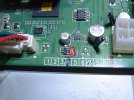
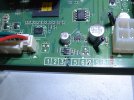
Incidentally, U551 (nearby) is a 64K serial 2-wire EEPROM. EEPROMs have been known to become problematic over time, but not in this case I think.
Attention has returned to the nearby electrolytic over which I placed a 1” long Hellermann sleeve. Fresh from the oven, squirting freezer down into the sleeve provoked the fault. I’ve now attached some monitor wires across this cap so that I can ‘scope the voltage across it and try adding another cap in parallel. Watch this space.
[Edited 18 Nov 2021 to add following and fifth attachment.]
Incidentally, U551 (nearby) is a 64K serial 2-wire EEPROM. EEPROMs have been known to become problematic over time, but not in this case I think.
Attachments
-
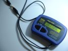
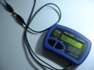
 2N4401 removed from good PVR.JPG324.9 KB · Views: 61
 -
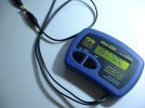
 Suspect 2N4401 removed from faulty PVR.JPG332 KB · Views: 55
 -
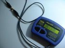
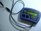
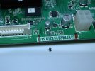
 Locating transplanted 2N4401 in faulty PVR.JPG332.7 KB · Views: 50
 -
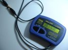
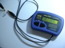
 Transplanted 2N4401 soldered in place.JPG322.9 KB · Views: 57
 -
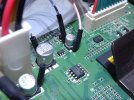 Monitor wires added to suspect cap.JPG322.4 KB · Views: 60
Last edited: