Start Up Fails When HDD Connected

there's a limit to how much work the board will take before tracks start to lift
Dead right

I think these SMD blighters have a little dot of glue on their underside which makes them more difficult to remove than might appear.
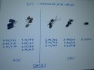
That would not be usual. The pre-applied solder paste keeps them in place, then the process of reflow eliminates any placement misalignment by the action of surface tension (in the molten solder). The components get pulled to the "centre of gravity" (for want of a better term) of the pad footprint.

Something you might not have taken account of is that the solder is lead-free and thus requires more heat before it melts (greater hazard to the PCB). It's easier if you add some tin-lead solder first.
 
It's easier if you add some tin-lead solder first.
Indeed. I pile-on some old-school solder to get the thermal mass up and then dislodge with a small flat-blade screwdriver once the solder on both sides of the component is molten - then clean-up using desoldering braid. Solder-suckers are an absolute no-no due to the significant risk of tiny fragments of solder being spattered across the board when the pump is released (with the attendant risk of shorts).

Re the glue dots theory, on other boards I'm sure I've seen tiny, hard pink dots in the centre of unpopulated components' footprints (so not solder paste, as on bare board rather than traces).
 
Re the glue dots theory, on other boards I'm sure I've seen tiny, hard pink dots in the centre of unpopulated components' footprints (so not solder paste, as on bare board rather than traces).
Dunno then, never seen that and my knowledge of automated assembly might be outdated. If there was no need to glue down components before, I don't really see why they would now (except maybe the underside of a double-sided board?).
 
Glue dots can be used to prevent tombstoning which will occur if the component pads are heated unevenly. This could happen if say one pad has a good thermal connection to a ground plane. It can also occur when a board is wave soldered where small components are partially in the shadow of a large component when the solder wave moves across the board. [Tombstoning is where the solder melts on one connection and the surface tension pulls the component into a vertical position]
 
on other boards
I meant other boards generally.

When removing the components from the faulty PVR's board as described, I found they didn't "float away" once the solder was molten - they needed a bit of a shove; that led me to think they had glue dots. And when I cleaned up the not-faulty 2N4401 before fitting it to the good PVR's board there was some hard residue on its underside which I scraped off with a screwdriver blade.
 
Something else to replace while I'm at it (we do use the SPDIF output). A common problem, I guess. The lead isn't a firm fit without the shutter.
 

Attachments

  • Broken SPDIF socket.JPG
    Broken SPDIF socket.JPG
    330.8 KB · Views: 14
I was "amused" to find the SPDIF port emits IR whether in use or not, as I discovered when I was using a phone camera as a mirror to see behind a unit. I guess this might be a non-contact way to detect whether a HDR is "on" or "half-awake".
 
Thought I'd check the other 4u7s in my spares drawer (at room temperature) - all the ESRs are well below 20R. See post #96 for the checks on the suspect cap, which strongly suggest it's seriously unwell.

[Edited 29 Nov 2021 to add following.]

When selecting a cap to fit as a replacement for the suspect one I realised that one of the three second from right is actually a 50V (same brand as, and similar size to, the other two 25V ones; similar ESR too).
 

Attachments

  • Other 4u7 checks.JPG
    Other 4u7 checks.JPG
    333.5 KB · Views: 22
Last edited:
That 4.7uF is in a 'Miller' soft-start slow-off circuit (along with the very slightly lossy 100uF electrolytic as a Zobel network) intended to prevent resonant over-volt spikes on the "long" inductive 12V power line to the HDD from damaging eiher the FET or the HDD.
Been there done that!
 
Zobel network
Famously, these series-RC networks are usually to be found across audio power amplifier outputs (as a sort of power-factor correction for the inductive load presented by the speaker) to aid stability. I recall, as a lad, absorbing all the useful info in the little white booklet that came with Clive Sinclair's "Project 60" modular stereo system - the importance of star-point earthing was stressed: http://rk.nvg.ntnu.no/sinclair/audio/project60.htm Interesting to raise the notion of a Zobel network in this context - that 100u is a bit more than just a bit of extra distributed decoupling, then.
 
If you’ve been following recent developments on this thread, you’ll know that I’m awaiting arrival of some Mosfets. Fitting a new Mosfet (to replace the one I blew up) and a replacement 4u7 cap (both in the HDD 12V switch, and the latter the likely cause of the problem captured in the title of this thread) should, fingers crossed, get our faulty PVR working properly again.

Meantime, we’ve been using our spare PVR. Despite being set up the same as the faulty one (unless I’ve missed something really subtle), I’ve noticed a difference in the clarity of the text when the Media – Video list is displayed (see below). For example, the left hand down-stroke of the u in “Rumpole” is grey, rather than white, whereas the right-hand up-stroke is the normal white (and compare the i and l in “Bailey”). The effect on slanted elements holds a clue, I think – maybe some clock/crosstalk problem? The faulty PVR never exhibited this problem. Apologies in advance if I’ve missed something obvious in the setup – but, for now, it looks like an inherent difference between the PVRs.

We’re definitely connected HDMI to the same TV input as before, so all a bit of a puzzle. Just wondered if anyone had come across this before. Same software on both PVRs – 1.03.12.

Spare PVR OSD problem.JPG
 
Check your V-FORMAT
Yep, that was it - many thanks. This doesn't appear to be a menu setting, just a dedicated button on the remote control (which is why I'd overlooked it). Sitting in the dentist's chair this afternoon I remembered that the other day I hadn't been able to select the aspect ratio "Just Scan" on our LG TV (I use this for minimum cropping of the picture) and on checking, the TV was displaying in 576p, so those artifacts were the result of the down-conversion. That V-FORMAT button is rather vulnerable to accidental operation; we surmised our Bearded Collie puppy accidentally changed the display format the other day by treading on the remote's WIDE button.
 
That V-FORMAT button is rather vulnerable to accidental operation; we surmised our Bearded Collie puppy accidentally changed the display format the other day by treading on the remote's WIDE button.
You can use the boot-settings package to force the format, among other options, to be set at boot time.
 
Back
Top