Start Up Fails When HDD Connected

Many thanks to Newcoppiceman for comments and guidance on making the repair on this forum

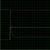
I attached an 256Gb SSD which only requires the 5v tom operate (to prove the issue was the a faulty 12v supply) and as expected the the box started up and recognised the SSD attached, no longer stuck in the "starting"

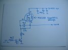
After that test, a few days ago, I then removed the old cap, soldered in a replacement 4.7uF one (not pretty as it is a leaded large electrolytic cap 35v rated that i pinched from an old maplin audio mixer i had knocking around),

I can therefore also confirm that capacitor that is the fault for this problem stated, nothing else has been done.

Also installed the custom firmware now after finding hummt.tv to fix the hardware , cant believe the features i've been missing for over 12 years, decrypt and detect ads!!
 
Like this?

as i said in my post, i had only electrolytic available to me, not this type
 

10-off 4.7uF 25V for £1.50 inc p&p. Wow! I don't know how they do it.

Expedited delivery available as an option.
 
Last edited:

10-off 4.7uF 25V for £1.50 inc p&p. Wow! I don't know how they do it.
Presumably the capacitor type or max voltage rating shouldn't be of concern for use in the Humax - either type should work.

Usually the ultra cheap free postage deals come from China but it does claim UK postage
 
Presumably the capacitor type or max voltage rating shouldn't be of concern for use in the Humax - either type should work.
Not sure. Voltage is no problem, the required working voltage is 12V so anything greater than that should be fine. The trade-off is size (the higher the rated voltage, the physically bigger the capacitor will be). Size is not specified in the eBay advert, but experience says a 25V 4.7uF can will be pretty small! Too large and there will be difficulty fitting it - the leads will be too far apart if nothing else.

The real problem is the ESR (equivalent series resistance), which will be different between a typical wet aluminium electrolytic and a solid tantalum. I do not know whether that would make a difference, nor whether lower is necessarily better.
 
The real problem is the ESR (equivalent series resistance), which will be different between a typical wet aluminium electrolytic and a solid tantalum. I do not know whether that would make a difference, nor whether lower is necessarily better.
ESR isn't going to be a relevent here - from the cct posted earlier it's got a 1k0 resistor in series with it after all and it's just slightly delaying the rise/fall of the +12V line.

I've not been as involved in this thread as I perhaps could been and I'm now wondering why this cap is there. If I saw it in isolation I'd read it as being there as an afterthought to give a delay on switch-off, not switch-on where it seems to be giving problems. I presume the control signal is under firmware control so any delay could be done there.

Has anyone measured the capacitance and leakage of a replaced one and has it only been on the V1 PCB with twin tuners? Also does the unit work OK without the capacitor?
 
I've not been as involved in this thread as I perhaps could been and I'm now wondering why this cap is there. If I saw it in isolation I'd read it as being there as an afterthought to give a delay on switch-off, not switch-on where it seems to be giving problems. I presume the control signal is under firmware control so any delay could be done there.
I think you might be right, that it is meant to delay switch-off. The reason it gives a problem during switch on could be that it has a high leakage current and therefore the FET doesn't get enough gate voltage.
 
If anyone is interested and has any thoughts/comments I have copied the circuit in to Proteus simulation software. As expected without the 4.7uF capacitor the switching is more or less instantaneous.
I include the oscilloscope traces for switch on and off of the HDD control, that is 5v and 0v input to 4k7 resistor feeding base of transistor (yellow), gate of MOSFET (blue) and feed to HDD (red). Vertical scale 1V division and horizontal scale 10ms division.
 

Attachments

  • HDD on.jpg
    HDD on.jpg
    105.5 KB · Views: 20
  • HDD off.jpg
    HDD off.jpg
    111.7 KB · Views: 21
Last edited:
Am I right in thinking that an easy test for this leaky capacitor would be a voltage on the gate of significantly higher than the expected 1.4ish V then?

BTW, your units are wrong (V and ms, not v and mS).
 
If anyone is interested and has any thoughts/comments I have copied the circuit in to Proteus simulation software. As expected without the 4.7uF capacitor the switching is more or less instantaneous.
I include the oscilloscope traces for switch on and off of the HDD control, that is 5v and 0v input to 4k7 resistor feeding base of transistor (yellow), gate of MOSFET (blue) and feed to HDD (red). Vertical scale 1V division and horizontal scale 10ms division.
Ta for that. The delays are exactly as I expected - no delay on switching HDD +12V on but a 50-60ms delay on switching off.

That cct appears on the DTR-T1010 PCB I have in front of me with a SOT-23 MOSFET marked 25D34, the NPN transistor has a 7k5 base drive with another 7k5 resistor base-emitter, plus there's an unpopulated SOT-23 position for something (diode?) connected from the NPN base to HDD +12V which is odd. Looks like it's a 4-layer board BTW.

So either delaying HDD +12V switching off is vital or it's been copied without thinking from earlier designs, which happens.

As to the issue of the booting loop being fixed by replacing the 4u7 cap, I can only think that either the cap is going massively leaky - has anyone measured a suspect one? - or the act of removing it clears a leakage path on the board. Electrolytics can leak electrolyte but there's hardly any in a cap that size.
 
Since my previous post I have, in the simulation, placed a variable resistor in parallel with the 4.7uF capacitor and it needs setting to a value of less than 400 ohms before it starts to reduce the output voltage, less than 350 ohms before the output voltage drops below 10 volts and 330 ohms for it to reduce to 7 volts. So if it is caused by the 4.7uF going leaky it should be measurable in circuit.
 
Last edited:
So if it is caused by the 4.7uF going leaky it should be measurable in circuit.
Indeed, assuming it's leakage and not something else.

The other obvious option is the value dropping, which would affect the delay on power-down. But that would seem to indicate that something happens late in the shutdown which if missed stops it booting correctly, which sounds unlikely.

So could it be that the drive to the NPN isn't constant at some point in the boot sequence and the 50-60ms delay is necessary to bridge it? I may rebuild this DTR-T1010, remove its cap and see what happens. The base-emitter resistor on the NPN is what one would add if whatever drives it may go tri-state so you don't want the base to float.
 
I can't see why that would be, it's well into the boot sequence by then... but that doesn't make it impossible of course.
 
It would be interesting to discover the outcome if someone who has a unit with this fault could just remove the 4.7uF capacitor and see what happens.
 
Last edited:
Great to see people getting stuck-in to this one again recently. See posts #96 and #143 for tests I conducted on removed caps. I've attached the drawing of the circuit I made during my investigations for reference. My HDR-Fox T2 has started first time, every time, since I replaced that cap over a year ago. I have two spare units, so expect to stick with the model until they finally pull the plugs on Freeview.

Incidentally, I do a lot of moving of recordings between folders but have learnt not to do this while it's recording as maybe 1-in-20 times it causes a system crash and the recording to stop (not fail, though).
 

Attachments

  • HDD 12V switch schematic.JPG
    HDD 12V switch schematic.JPG
    322.6 KB · Views: 15
Back
Top