Start Up Fails When HDD Connected

RichFX

New Member
I agree. I can see that if the SM cap is leaking a tiny bit of current then the FET might not have enough gate volts to turn on fully, and then higher peak demand on the FET by a busy HD could cause a problem.

I don't have the right tools to hand to guarantee success and just tagging it "seems" to work. But the second machine I fixed has died again while on soak test so I thought I'd do as you recommended, and since it is only a spare what have I got to lose?

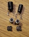
First pic is with SM cap removed, phew, and next pic is with another new 4.7uF leaded cap.

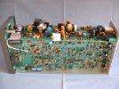
But... I should have checked all the supplies to the HD first because the +5V is missing, while the +12V is switching OK. Both are OK leaving the PSU card, so I need to find the +5V control chip. I remember it has been mentioned in this thread. Off for a look.
It looks like this one needs a new 5V chip. Input supply is 5.81V, but the feedback control pin is only 0.77V when it would be 1.25V if regulating correctly.

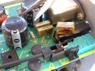
It looks tricky to remove without also removing the plastic HDD power plug so close. I need to buy more gas for my pyropen.

I may be some time fixing this one. :(
 
OP
Black Hole

Black Hole

May contain traces of nut
That's interesting, because it sounds more like the fault I was looking into in the first place, and which got overtaken by the capacitor fix.
 

RichFX

New Member
That's interesting, because it sounds more like the fault I was looking into in the first place, and which got overtaken by the capacitor fix.

I fear I may not find enough time or enthusiasm to fix T2 no.2 as a total dismanling is needed to remove the HDD power plug, not a quick fix.

However this evening's exercise was not entirely futile. Taking off the 4.7uF capacitor was very much easier than I expected.

I fiddled about for a while on T2 no.2 masking off the surroundings from the SM C, then I had a lightbulb moment and realised how very thin the capacitor's internal wires would be compared with its SM tags soldered to the PCB pads.
So I gently, gently rotated the can back and forth on axis, no great force and it gradually eased, travelled further each twist, and eventually snapped off. The wires inside it are a mere 0.2mm according to my calipers.

Then it was easy to clean off the remaining SM tags from the PCB pads with couple of quick touches from a trusty old Weller TCP.

I've re-done T2 no.1 properly now. A fifteen minute job including unplugging and re-plugging and shaping the leads on the new C. OK so far.
 
So I gently, gently rotated the can back and forth on axis, no great force and it gradually eased, travelled further each twist, and eventually snapped off.
Nice work. Always worth considering the best way to remove a dud component. I used a similar technique recently after the Tektronix PAL vectorscope I was refurbishing made an interesting noise and started emitting copious quantities of the magic smoke - a filter cap across the mains input had died. I didn't fancy the work involved in removing the large PCB so waggled the cap until its leads fractured, then soldered a new (Class X2 type) to the plated-through holes (which I knew I'd find beneath). The board cleaned-up quite nicely.
 

Attachments

  • 11.JPG
    11.JPG
    334 KB · Views: 11
  • 8.JPG
    8.JPG
    324.8 KB · Views: 11
  • 2.JPG
    2.JPG
    320.2 KB · Views: 11

prpr

Well-Known Member
I used a similar technique recently after the Tektronix PAL vectorscope I was refurbishing
No diff phase there then, although the burst phase is a bit off. Is that Set90 or Set180 that needs a tweak... I forget now.
started emitting copious quantities of the magic smoke - a filter cap across the mains input had died...
Mother's food mixer/beater thingy suffered the exact same problem. She turned it off at the wall rather than on the device (she almost always did), then phoned me asking what to do and whether to try turning it on again. I said NO!
then soldered a new (Class X2 type)
Having removed the defective C, I was amazed to find the exact same part in the spares drawer. Fitted it and been working ever since, which is sadly more than can be said about her cooking days.
 
although the burst phase is a bit off
Yes, well spotted! The bars were coming from a Snell & Wilcox TBC11P set to output a test signal (also does multiburst) - could be its coder needs a tweak, rather than a problem with the vectorscope (which I haven't tweaked at all).
 

RichFX

New Member
So cutting through the cap above the base with long-nosed snips would work?
Maybe. But I think a lot depends on how thick the wires are and how messy cutting through the cap might be.
Here's s pic of two twisted off SM caps and their bases (less tabs) next to a couple of junk-box mini-caps I had tagged on previously.
You can see how thin the wires are, and a couple still with a tiny bit of solder from the tabs.
 

Attachments

  • 20230308_131855_c.jpg
    20230308_131855_c.jpg
    134.8 KB · Views: 12

RichFX

New Member
t looks like this one needs a new 5V chip. Input supply is 5.81V, but the feedback control pin is only 0.77V when it would be 1.25V if regulating correctly.
I had another look at T2 no.2 after studying the LDO reg data sheet again, and the feedback pin 5 is doing the right thing because the control pin 1 is low. I'm not going to be able to find where this signal comes from without a circuit.

Even without HDD this signal never appears. The T2 never gets as far as lighting front panel or showing boot loader on HDMI output. So there is an upstream problem in system controls.

Alas my diagnostic skills are down to about 1% of what they were thirty years ago.

The sad thing is that it did sort of work when I was given it, and I've not done anything silly with it!

My mains socket includes a power meter and this gives quite a good indication of how far through the boot sequence a box travels. This T2 only reaches about 16W and stalls there.

My "working" T2 no.1 goes 16W (boot screen) 21W, 48W (briefly), and settles at 22W SD or 23W HD.
However while this one will always record on schedule from deep sleep (0.5W) with video output off (16W) it has an intermittent problem with the display output being misplaced vertically and offset horizontally differently above and below the "blanking" being shown on the raster! eg here
Just sometimes it will stick at 20W when told to shutdown.
 

Attachments

  • 20230309_144629_c.jpg
    20230309_144629_c.jpg
    160.5 KB · Views: 11

Chris humax

New Member
Maybe. But I think a lot depends on how thick the wires are and how messy cutting through the cap might be.
Here's s pic of two twisted off SM caps and their bases (less tabs) next to a couple of junk-box mini-caps I had tagged on previously.
You can see how thin the wires are, and a couple still with a tiny bit of solder from the tabs.
I used the cutting the top off the cap method because i feared damaging the board. My cutters are very small & sharp. But i just found a scrap humax board (DTR-T1010) with similar caps & used a gentle twist backwards & forwards & got good results on each cap. I didnt force anything & just continued till they came off.
 
Top